Overview
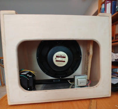
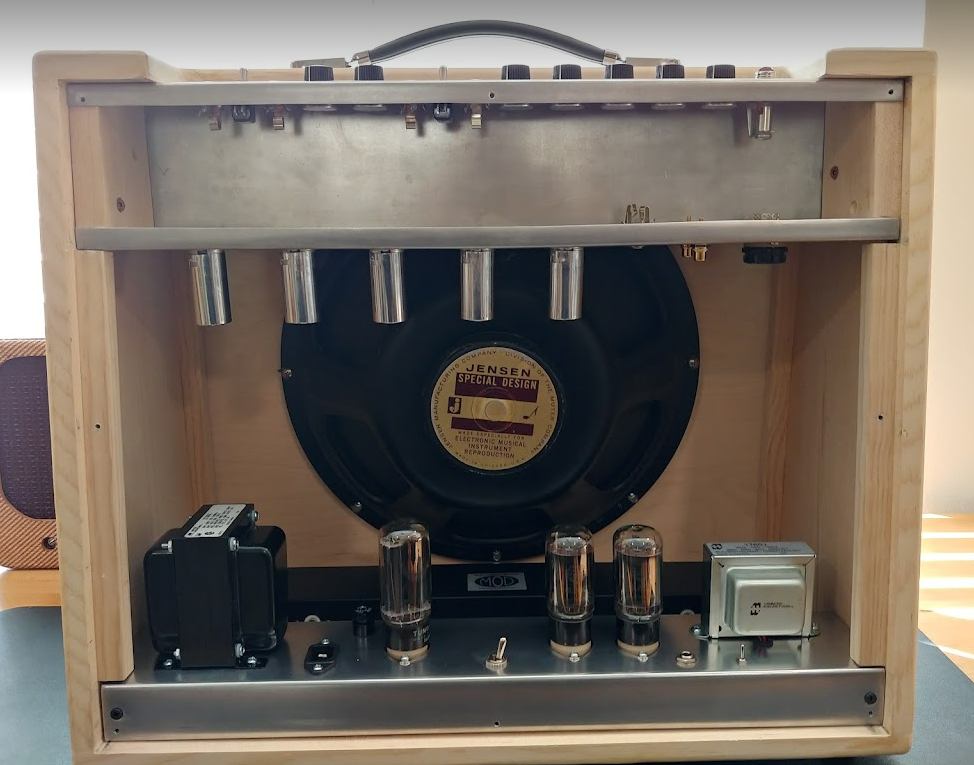
The Supro 1696TN reproduction combo amp started with the 15" Jensen speaker from 1966. I decided to build the amp around the speaker. Zach helped by constructing the cabinet which is very unique being a slant front and back. And I made the split chassis from scratch.
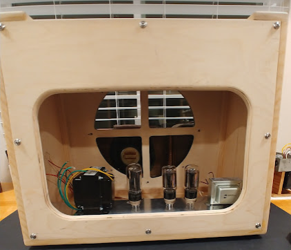
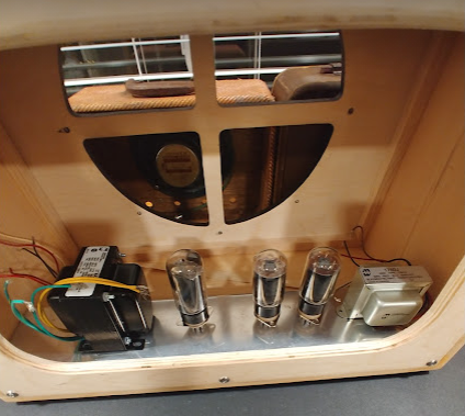
The 1696TN is a split chassis design with the power section on the floor and the preamp/tremolo section on the top.
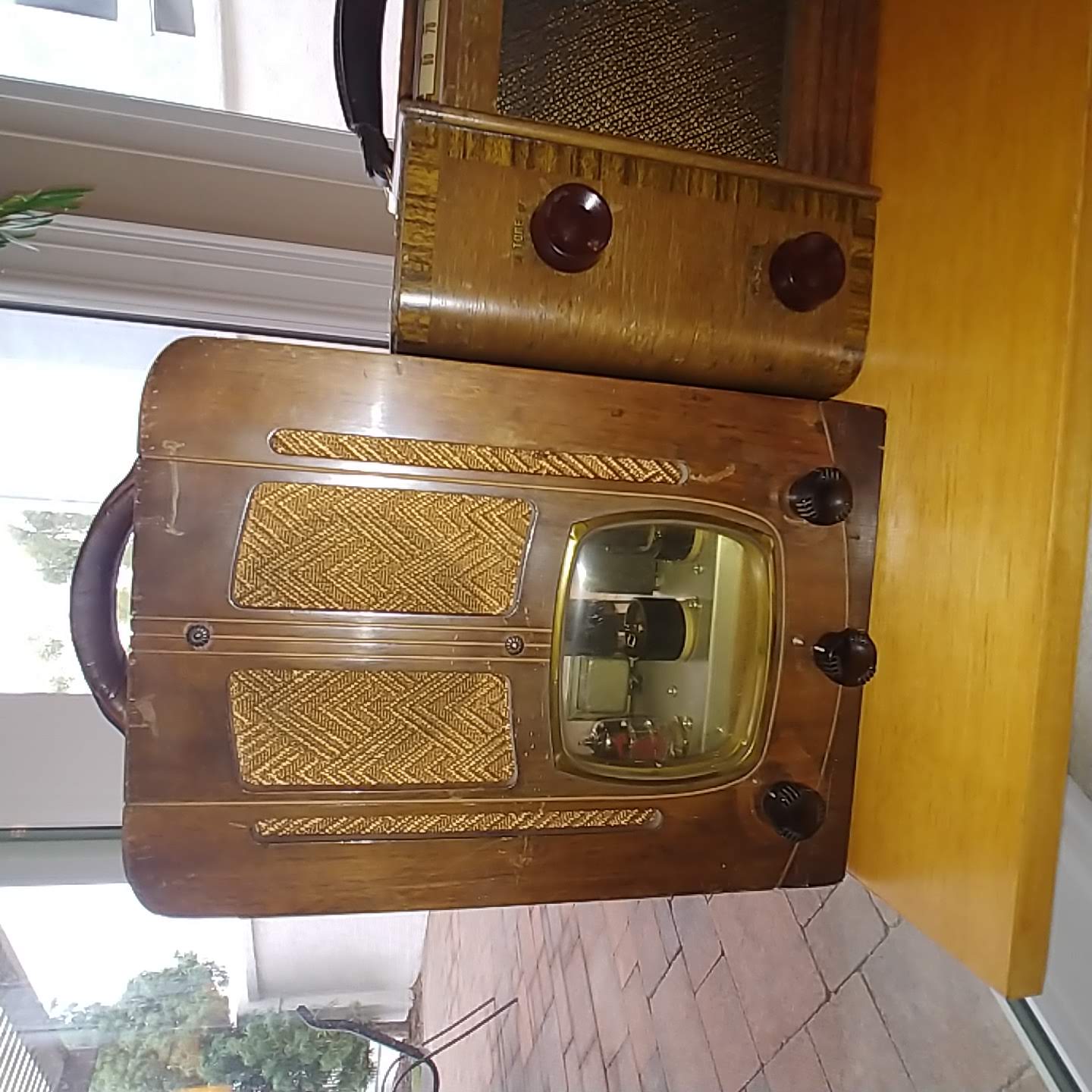
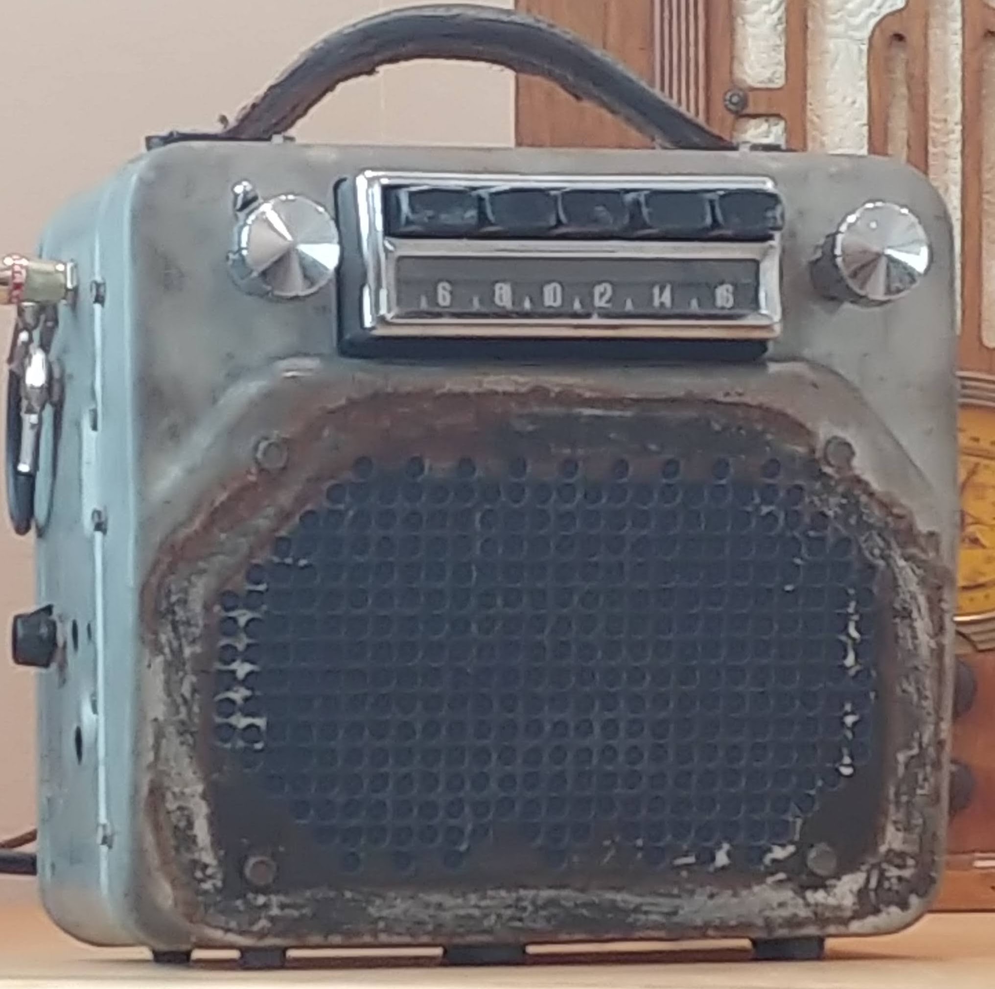
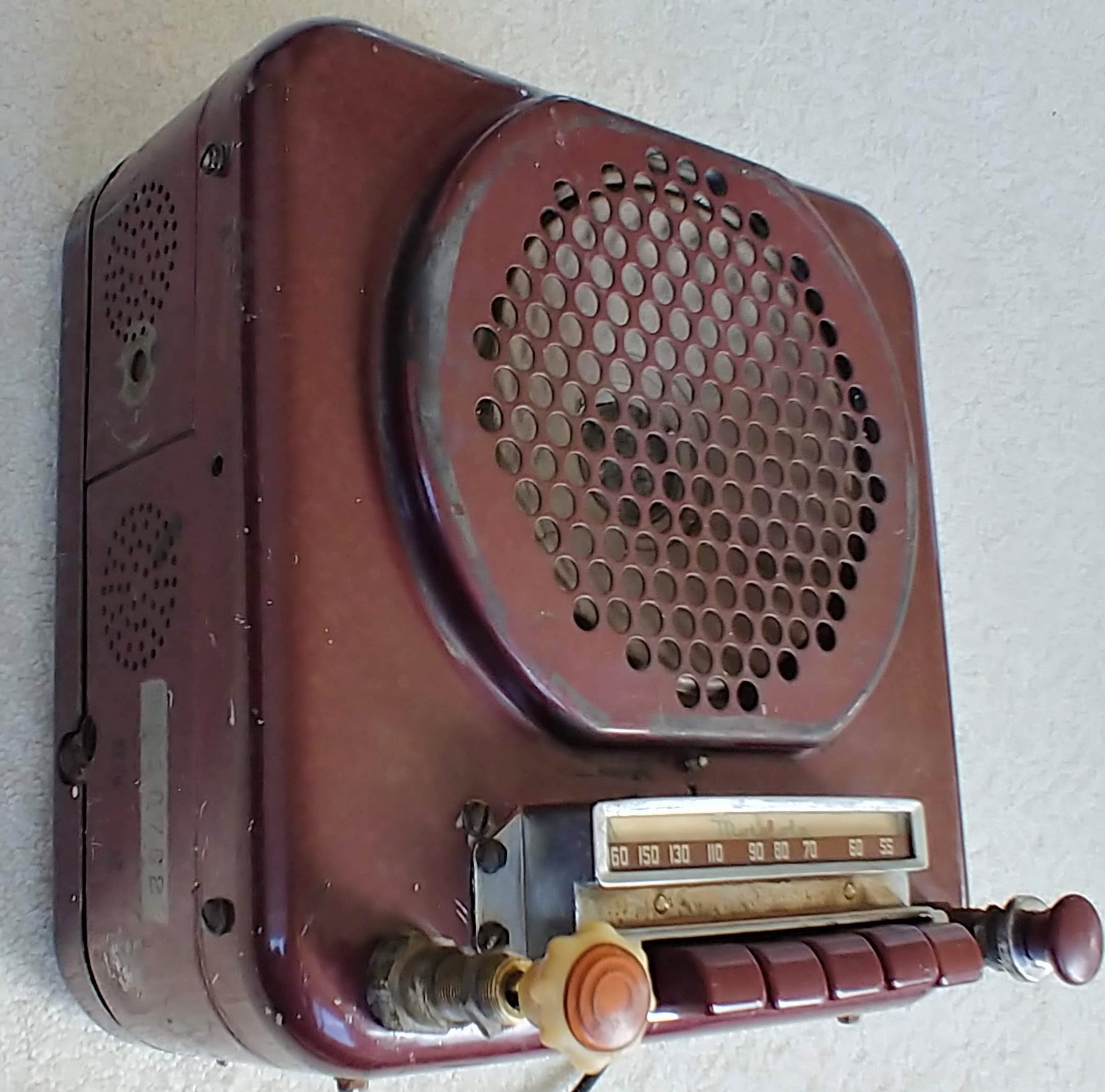
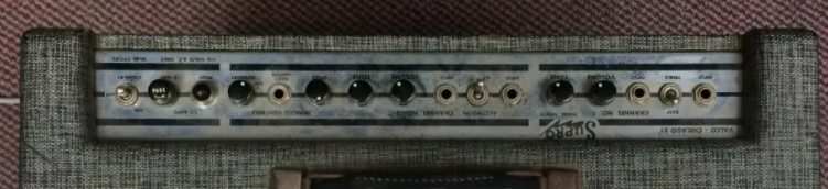
Original Supro 1696TN
Original Supro 1696TN
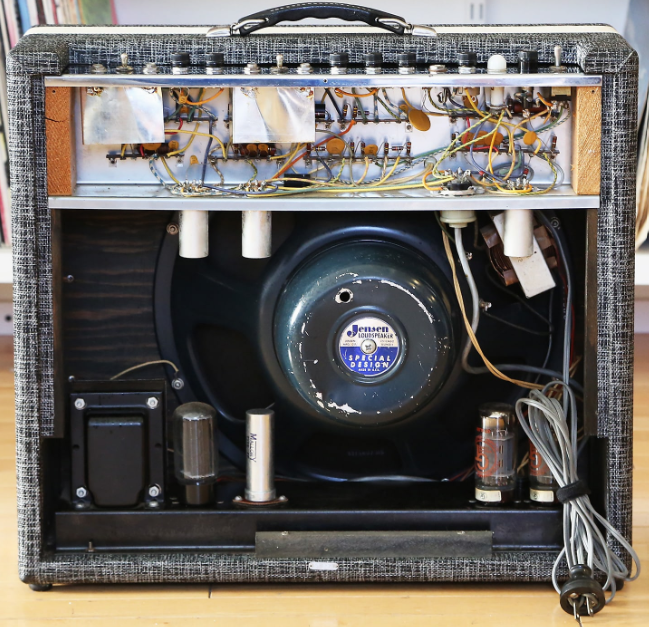
The reverb tank lives on the floor with the power section. Reverb is not native to the 1696TN, but is a nice feature addition.
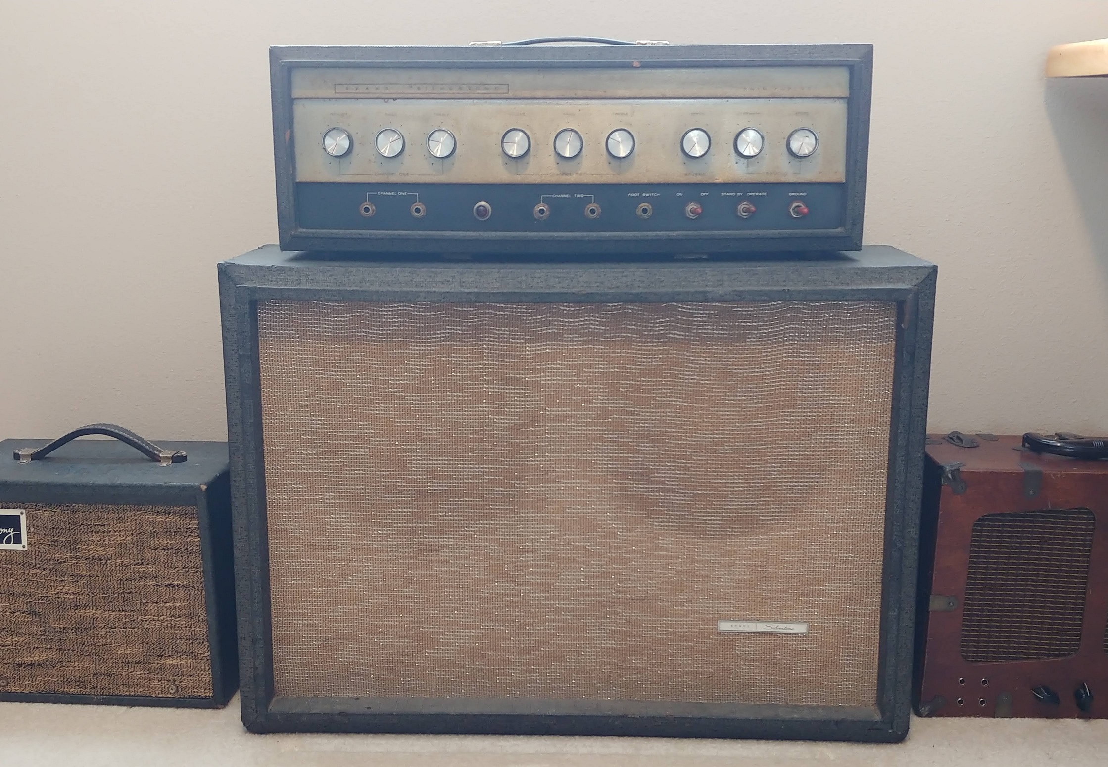
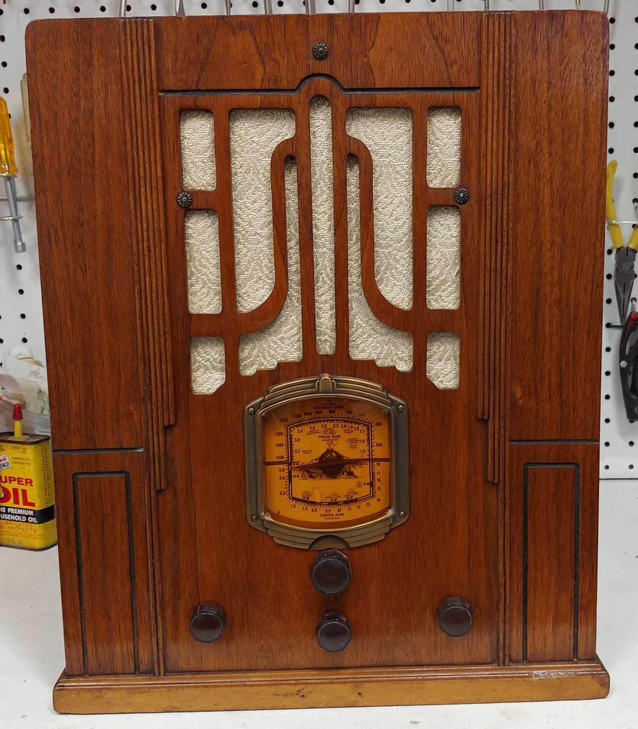
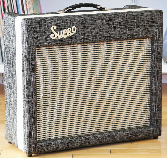
Inspiration
This amp is a hybrid taking the best of the Supro best. The cabinet is the slant front and back that Supro used in the Thunderbolt. While the split chassis and circuit is taken from the uber rare 1696TN. A reverb tank is added with the circuitry style found in the Fender Pro Reverb and Twin Reverb,
Cabinet
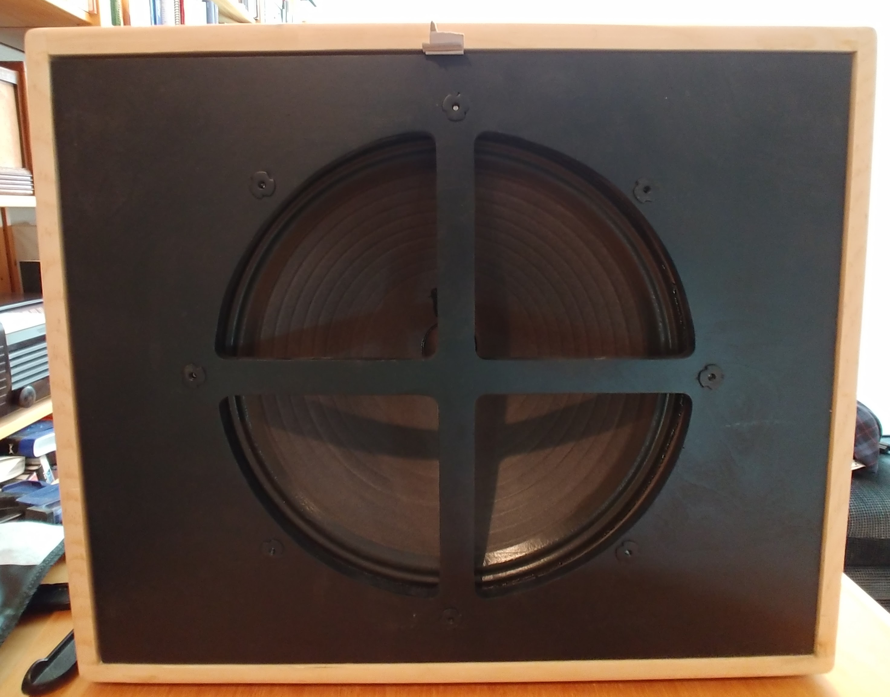
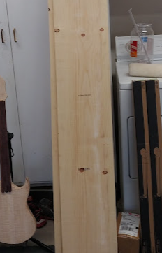
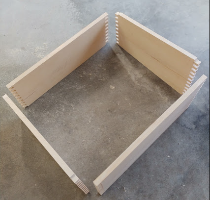
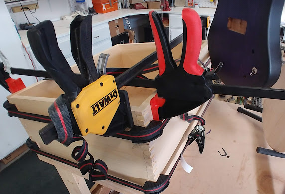
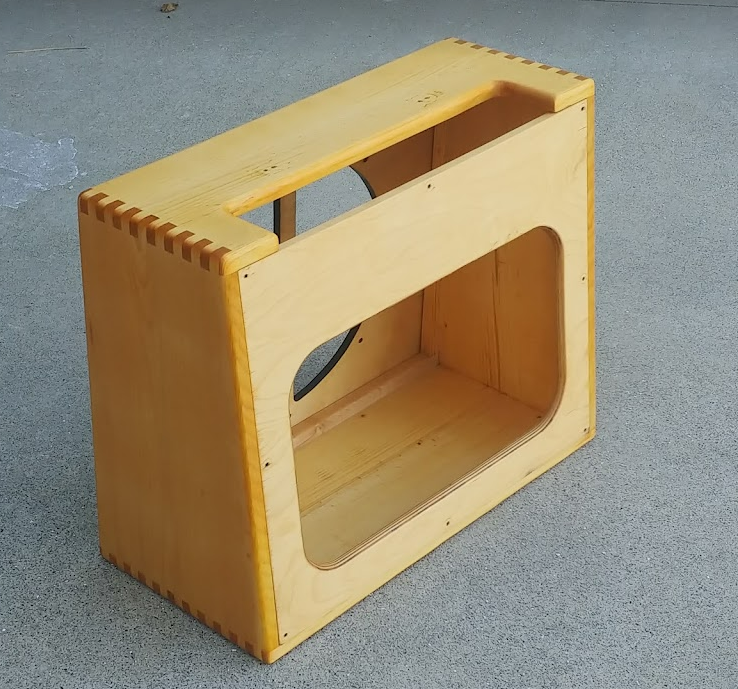
Starting with sugar pine the sides are cut between the knot lines so that the wood used in the cabinet is clear. Finger joints are cut in each end and the sides are glued and clamped. Once solid, the corners are rounded over and and sanded smooth. Next the rear panel and speaker baffle are cut from baltic plywood.
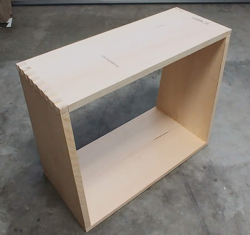
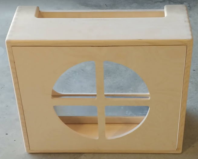
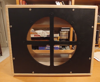
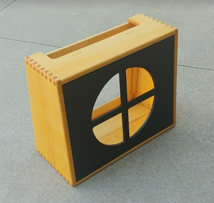
The 15” speaker baffle is cut in the style of Supro 6420 with a cross pattern. Some say that this adds to the Supro sound and my be acting as a beam blocker
Component Layout
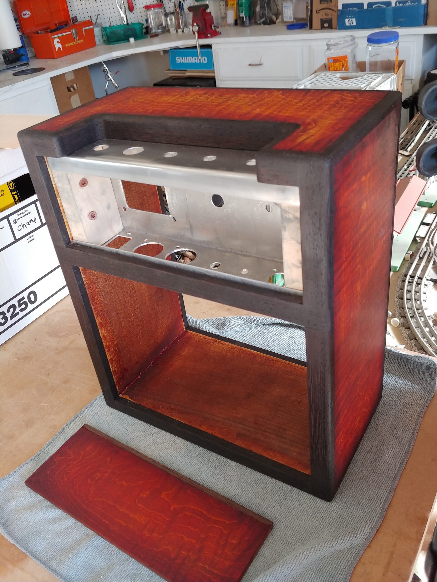
Cabinet FInish
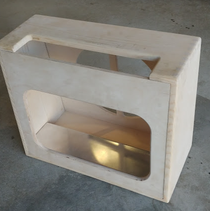
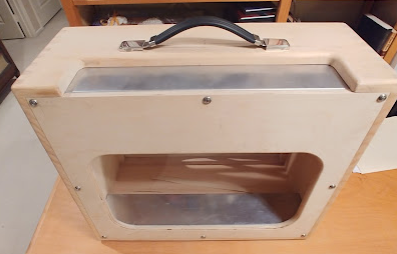
The cabinet is finished in boiled linseed oil (BLO) in order to bring out the beauty of the wood without the hassle of worrying about uneven stain absorption characteristic or pine cabinets. To date there are 5 coats of BLO. Apply with a brush, let it sit for 15min, wipe excess off. All cabinet hardware, speaker and chassis have been pre-fit and removed for the finishing,
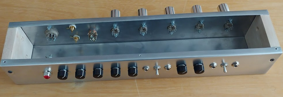
The panel layout will be important because there are so many parts to consider for design and function and they are an especially tight fit
Chassis
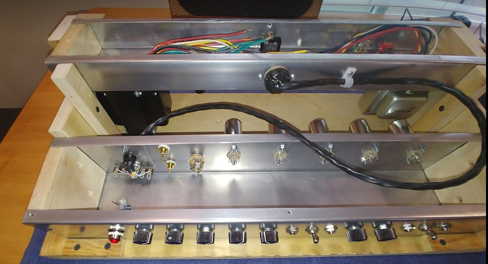
The chassis is a split chassis design used by Supro in their 1696TN. The power supply and power tube sections are housed in the floor chassis, while the preamp, phase inverter, tremolo and reverb circuits are located in the top chassis.
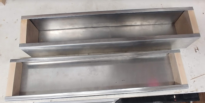
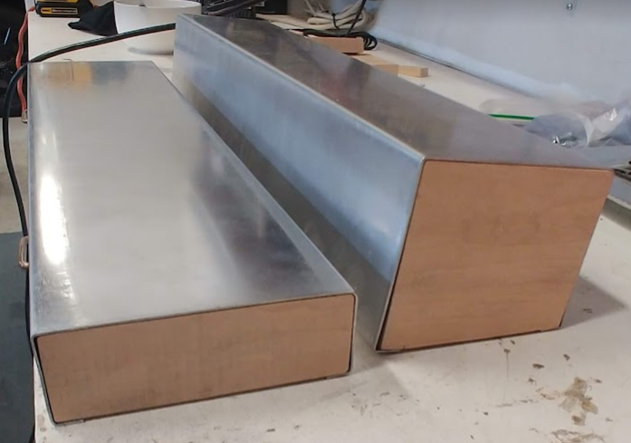
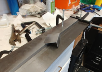
The chassis started as a sheet of .050 aluminum that was bent to the correct size. Maple blocks are used for each end. Because of the slant cabinet, the top chassis needed to be bent such that the bottom was slightly wider than the top to follow the slant of the cabinet.
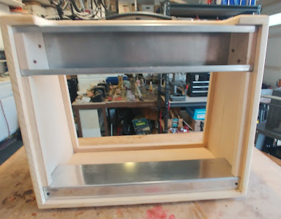
The maple end blocks are screwed into the aluminum plate and then the assembled chassis is attached from the inside to the cabinet. The bottom chassis is attached from the bottom of the cabinet floor.
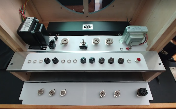
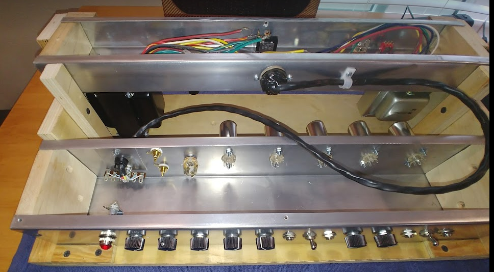
Here the Split Chassis is mounted in the custom build chassis jig ready for wiring
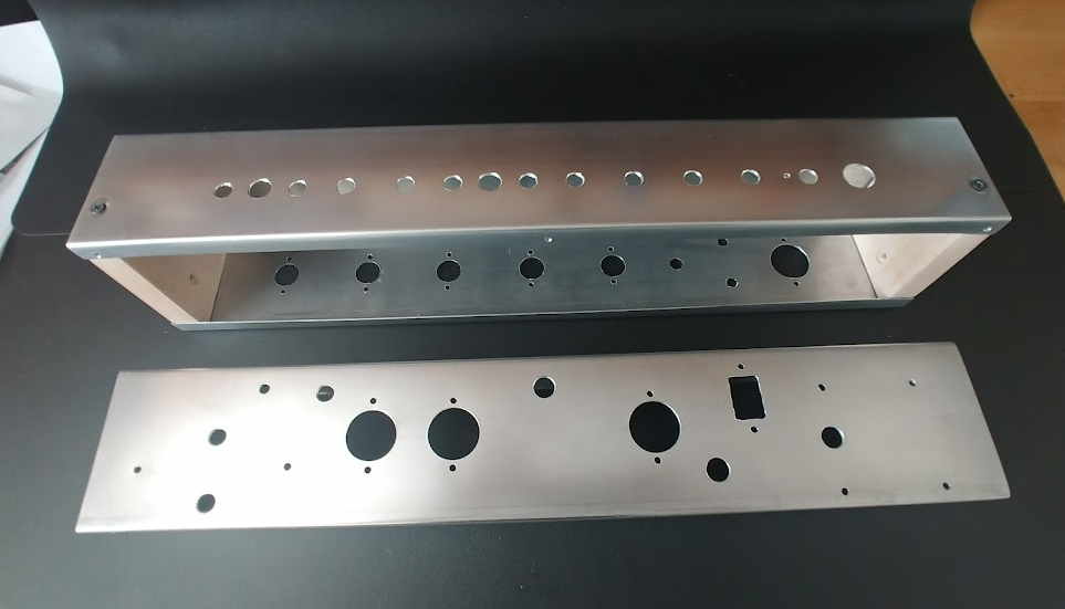
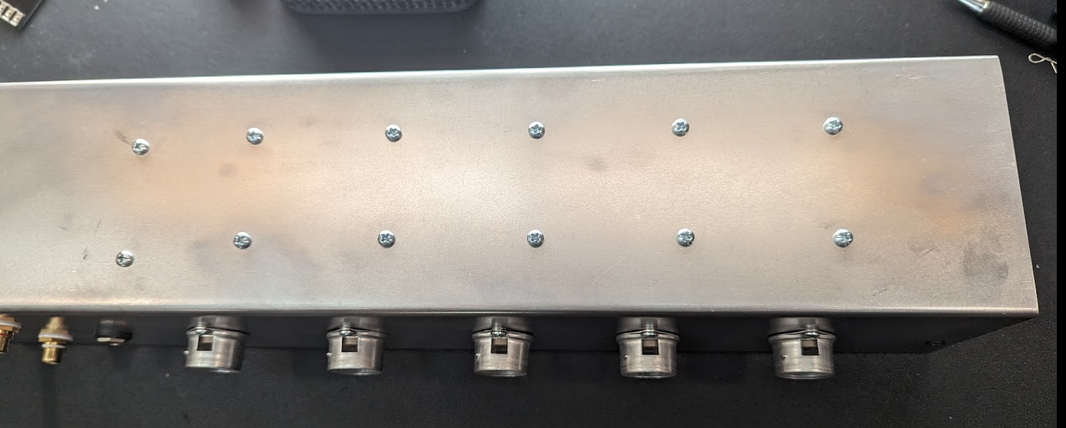
Top Panel
The original 1696TN control panel is shown below. The cutout for this project is intended to match this opening, but since I did not have an original amp to use for measurements. I scaled from the diagram as best I could? The finished opening is 17” x 2.75”. The project amp includes some modifications to accommodate the reverb control as well as removing the power switch and fuse to the lower chassis to avoid having to run mains power to the top and then to the lower chassis.
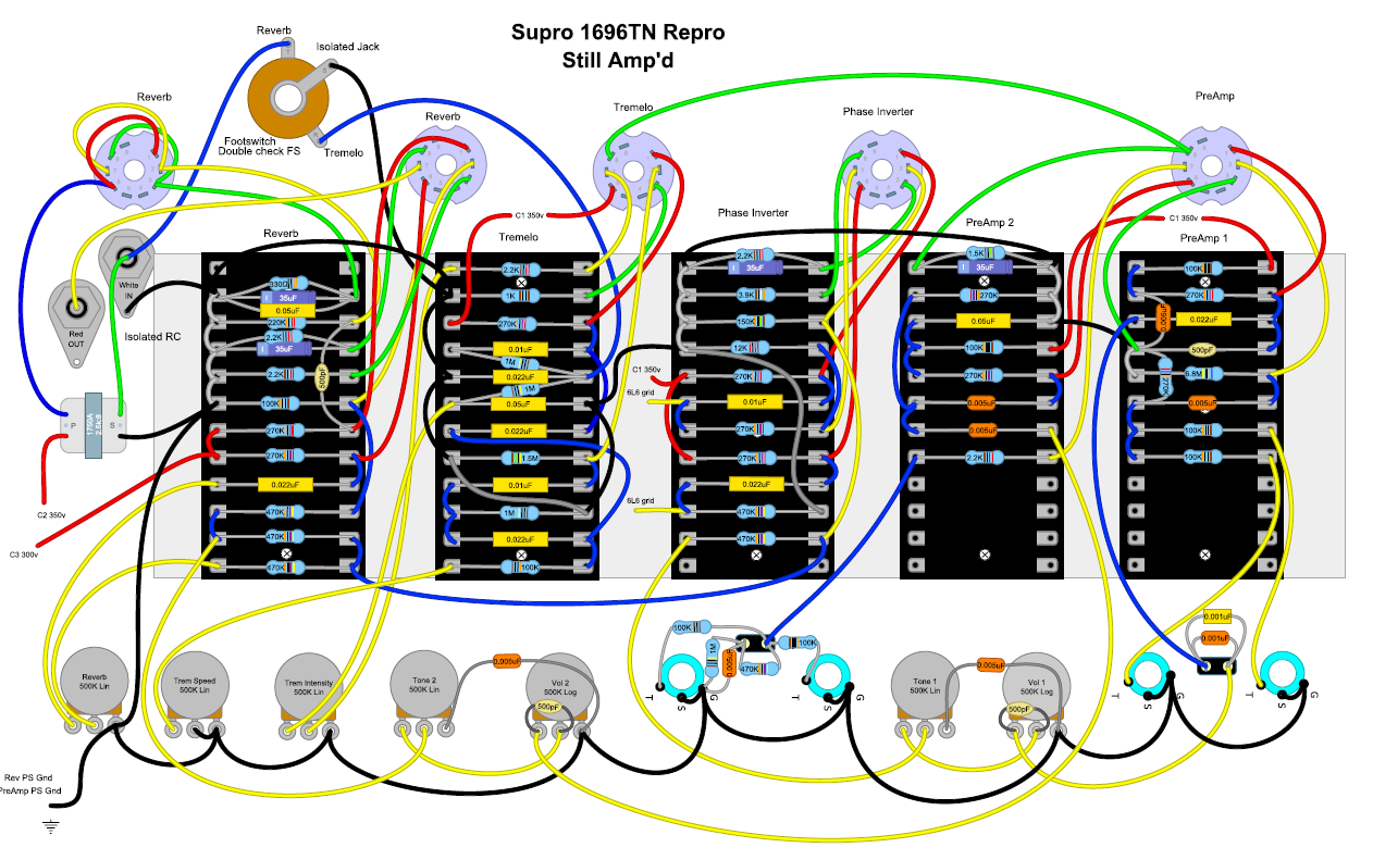
Circuit Design
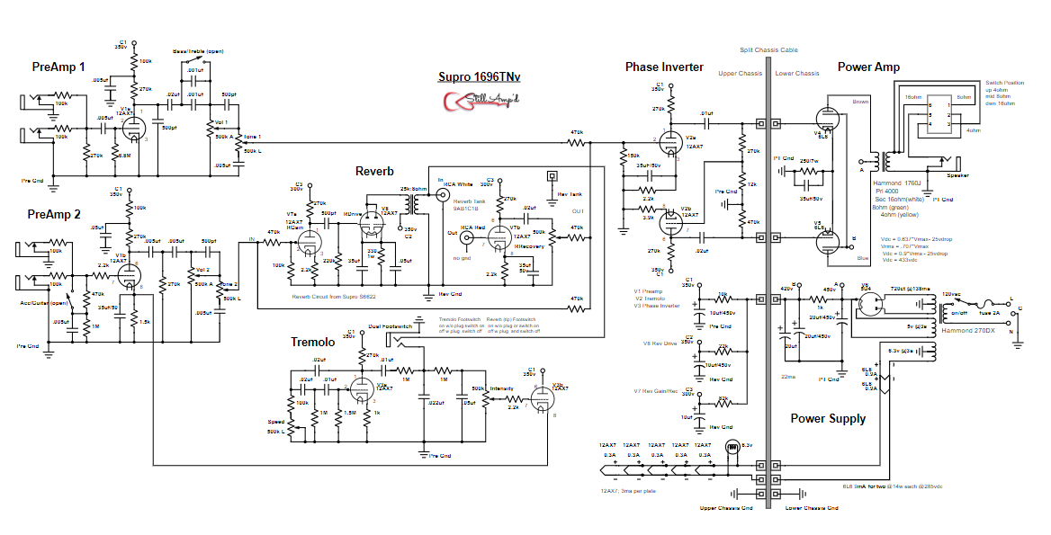
The manufacturer's schematic for the Supro 1696TN was not available. A couple of schematics that were hand drawn by Leon C and Bill Kahle were available. These schematics were replicated from Supro 1696TN amps that they owned. Steve Luckey (sluckey) the moderator from the EL34 forum created a computer generated design from these hand drawn schematics. As well as to offer some great advice. The diagram below added the reverb circuit (from the Supro S6622 to keep it within the Supro family) as well as to show the split chassis cable. This schematic is how the Supro 1696TN Repro is built. Several edits were included:
1 An impedance selector switch was added to allow the output transformer tap to be selected to match the speaker in use
2 A dual footswitch was added to allow selection of tremolo or reverb
3 The standby switch was removed
4 The on/off switch and fuse was housed in the lower chassis to avoid moving AC into the upper chassis
Power Transformer
Lots of great advice from the EL34 forum. Landed on the Hammond 274AX based on the discussion on this topic Picking the Right Power Transformer (see reply #10). The Hammond is an affordable and available option to the discontinued Classictone 40-18060 which was made as a direct replacement for this type of 6L6 Supro/Valco amp.
Output Transformer
Again lots of great advice from the EL34 discussion forum. It was decided to go with the Hammon 1760J OT because it has a primary impedance of 4000 ohm into a tapped secondary which is switch selectable for 4/8/16 ohm. The OT is rated at 40 watts. There was discussion that the primary impedance should be more in the range of 6k to 8k, but it was difficult to find this OT with variable output taps. The 1760J was represented as a Fender Bandmaster replacement which also used 6L6 in push-pull. As well Fender used 4k primary for many of their other 6L6 PP amps, so it was felt that this would be a reasonable way to go. Also, the Classictone 40-18061 was claimed to be an exact replacement for the Supro Thunderbolt with a 5k primary
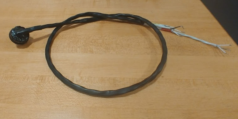
Split Chassis Cable
The cable that connects the lower power chassis with the upper preamp chassis was constructed using a 8 pin octal connector and socket. The cable includes three Shielded Twisted Pair (STP) to carry the lines. One STP includes the push-pull signal from the Power Inverter in the upper chassis. The Second STP contains the 6V heater power from the lower chassis. The third STP carries the preamp tube HV from the lower chassis. The entire cable is heat shrinked. On the upper chassis it has strain relief and is connected to a terminal strip. A mistake in the original design moved the connector to the lower chassis so that HV is not exposed in the connector pins. The upper chassis hole was plugged with a special designed custom aluminum plate.
Wiring the lower chassis
The power supply filter
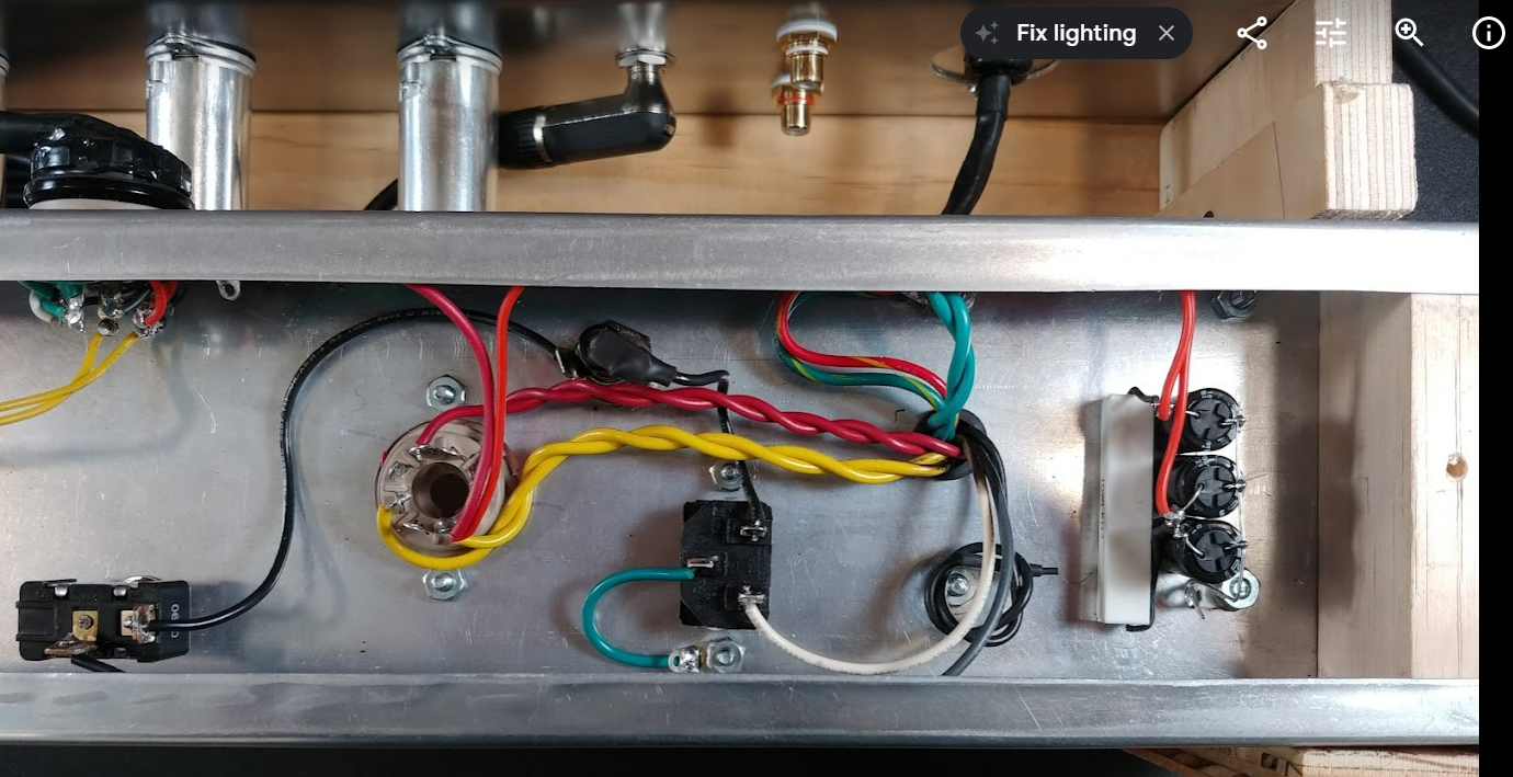
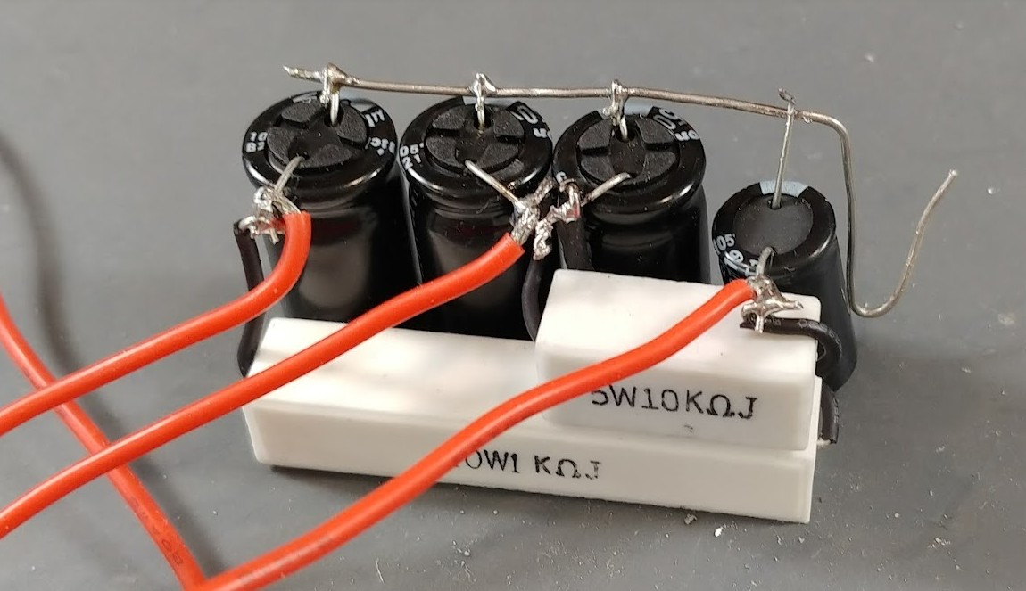
My style has been to forego the circuit board approach to hand wiring and use the technique of point to point. This is how manufacturers in the ear;y 60’s and before wired their amps and for me it gives a bit of artistic and technical routing. It also reduces the additional trouble of fabricating a circuit card. I believe that amp manufacturers adopted this approach so the could mass produce their product. But for me it does not have a lot of value for less complicated amp designs. And it gives me more freedom to run layout and change as needed. For me, the most challenging area of point to point wiring is the layout of the power supply filter. In the day, manufacturers would use cans that contained three or four capacitors and they just needed to mount the can and wire it up. But I use individual caps. I use radial leads because then I can stand them on end as I did with the 1696 design shown below. I couple of high wattage dropping resistors and a ground bus complete the design. The three red leads are for the 6L6 plates and screens and the preamp plates.
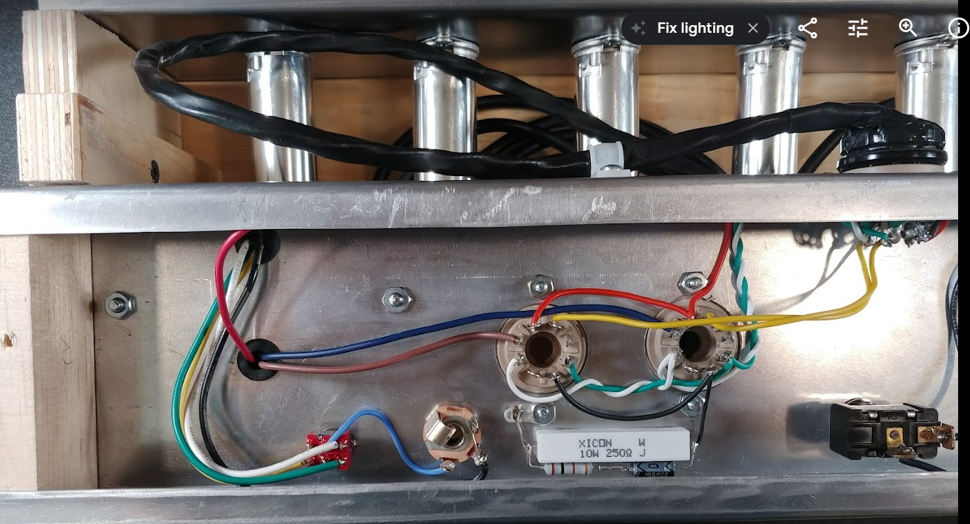
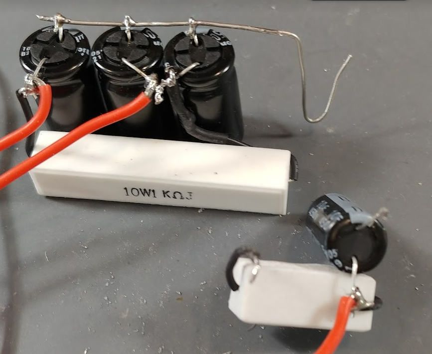
After building the PS Filter above I found out that the reverb needs 440v on its drive tube (which is in the upper chassis) and since I only allocated one HV line in the split chassis cable, I decided to send the middle voltage (about 420v for the 6L6 screens) through the cable and add the dropping resistor and capacitor for the preamp tubes in the upper chassis. The picture below shows this being removed.
Wiring the Upper Chassis
A perfect sized terminal board was sourced, it is 3x1.5” and allows for 12 components to be mounted. One termina board was allocated for each of the 5 sections in the upper chassis: PreAmp Channel 1, PreAmp Channel 1, Phase Inverter, Tremolo and Reverb.
Terminal Boards Mounted
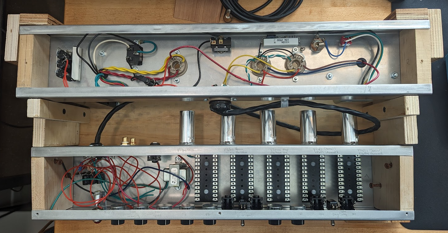
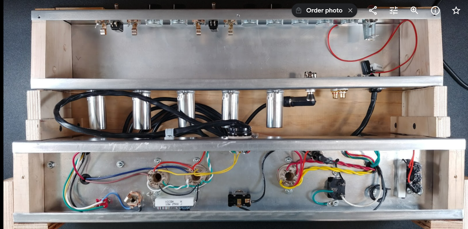
Lower Chassis Layout
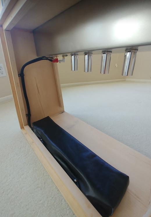
Reverb
This Supro 1696TN will have a reverb unit in the style of the FEnder Twin Reverb AB763. The tank is housed in the bottom of the cabinet in front of the lower power chassis and has its RCA cables running up the side to meetup with the upper pre-amp chassis that houses the transformer and the reverb tube and circuit. The tank has a custom designed bag that fits the tank perfectly created from the original bag provided with the Mod Tank.
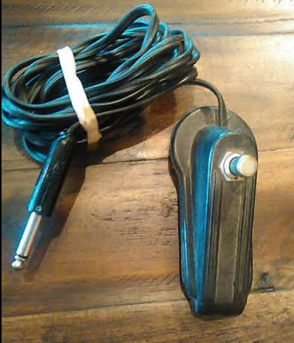
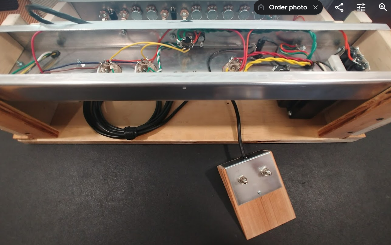
Footswitch
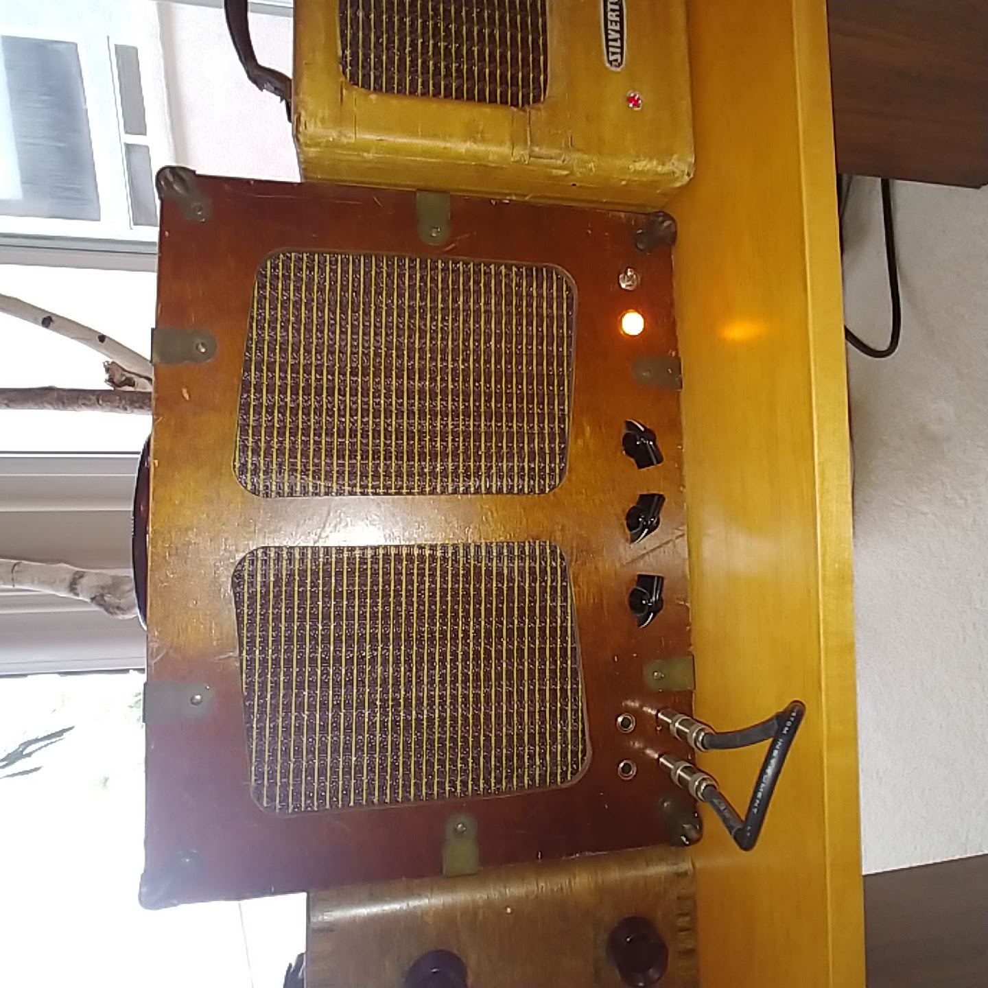
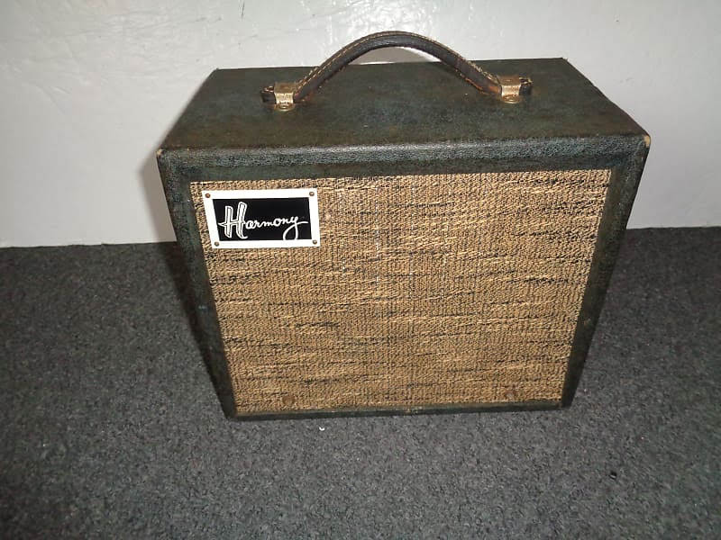
The original Supro 1696TN came with a single button switch for the tremolo shown in the picture below.
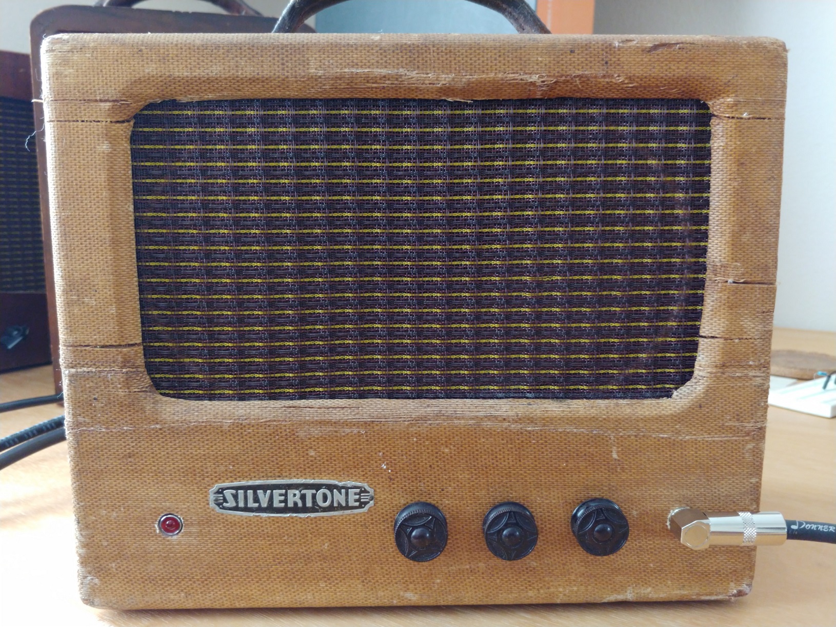
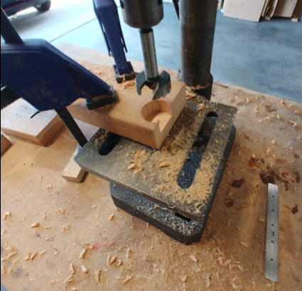
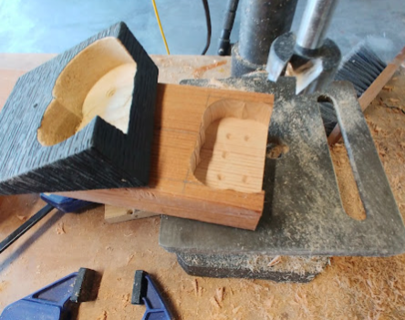
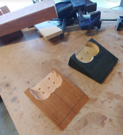
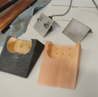
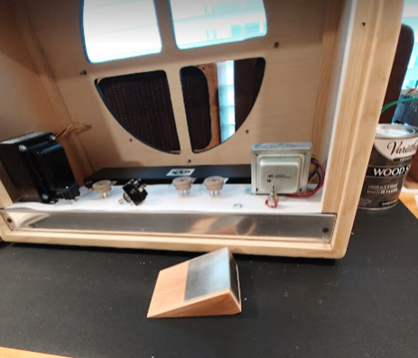
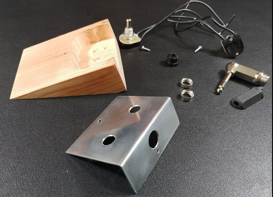
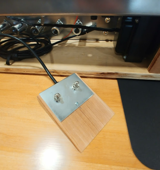
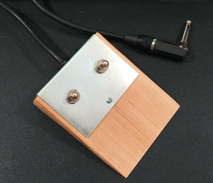
I decided to fabricate one in the style of the Danelectro/Silvertone amps of this era. I used an original Danelectro footswitch from this sites Silvertone 1484 restoration project as a model. It is constructed from a block of wood and aluminum plate. The cavity was “carved” using a Forstner bit with the block clamped to a drill press table. The wood block angle was carefully cut on a band saw which was challenging as the cut was made on the edge of the 2x4 block. Care and patience resulted in a nice precision angle in the style of the original. The aluminum plate was cut from stock aluminum sheet and bent with a brake. A great Thanksgiving Day 2021 project.
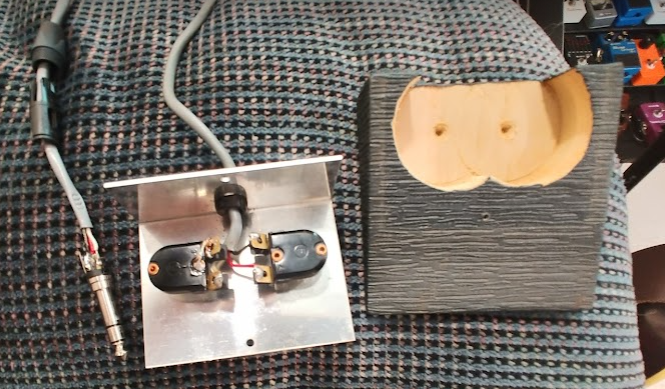
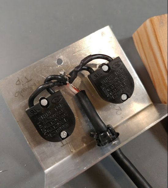
Here is the footswitch with panel holes drilled and with the switches and cable mounted. I used a flexible microphone cable for this design with two conductors and a shield for the ground return.
References
1 https://www.thegearpage.net/board/index.php?threads/supro-1696-tn.1481300/
3 https://reverb.com/item/6593941-supro-1696tn-thunderbolt-1960-s