Motorola 38-0
The Motorola 38-0 is a car radio from 1941 (see 1948 Servicing The Modern Car Radio from Murray Hill Books). The radio was in the 1941 Oldsmobile. The Repair Diary for this radio can be found in Antique Radio Forums here. Additional pictures from this restoration can be found here. The radio is showcased at Radio Museum here.
An extremely rare radio as there was very little written online about this radio prior to this acquisition.

History
The Motorola 38-0 Motorola Inc. ex Galvin Mfg.Co radio is a 6 tube Superheterodyne with RF-stage; ZF/IF 262 kHz; 7 AM circuits Tuned circuits
Wave bands Broadcast only (MW).
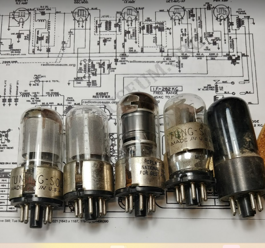
Valves / Tubes 6SD7GT 6SA7GT 6SK7GT 6SQ7GT 6U6GT 6X5GT
Requires 6v DC input. The loudspeaker is an Electro Magnetic Dynamic LS (moving-coil with field excitation coil) 6 inch; Vibrator for +B. Rider's Perpetual, Volume 12 ca. 1941 and before
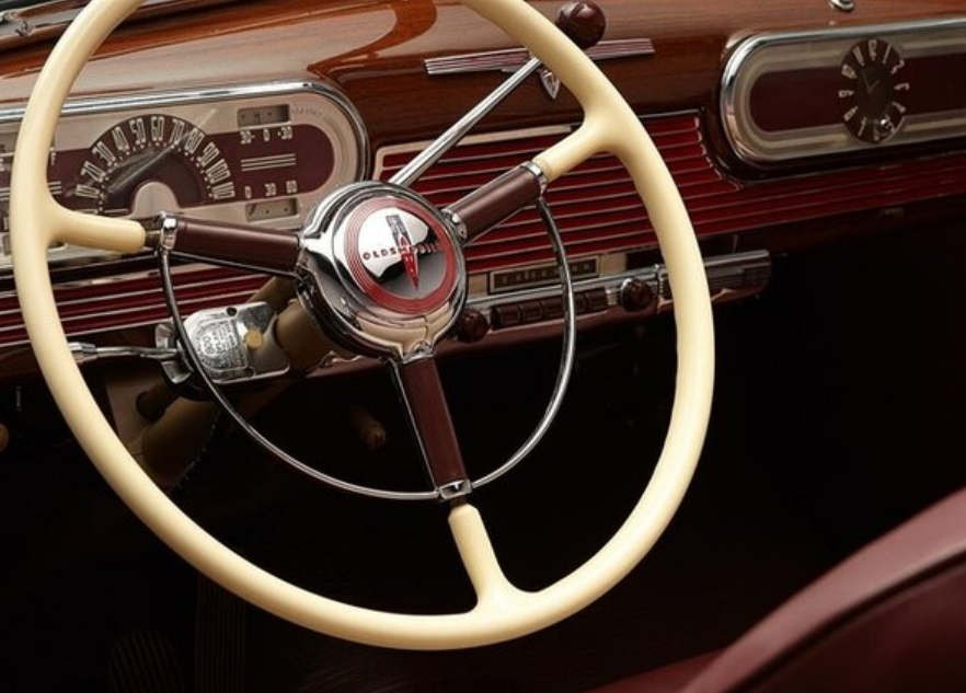
The 1941 Oldsmobile that the Motorola 38-0 radio was originally found in.

How the Motorola 38-0 Radio looked inside that 1941 Oldsmobile dashboard
Motorola Logo History
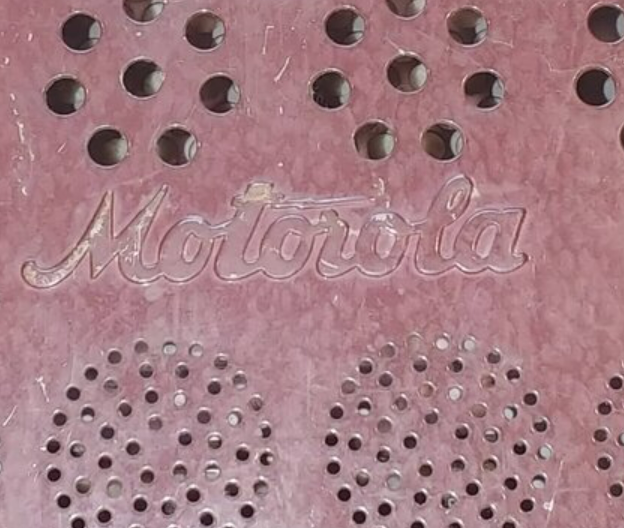
A bit of Motorola History as related to this radio. The diagram below shows the evolution of the Motorola brand through the years https://1000logos.net/motorola-logo/
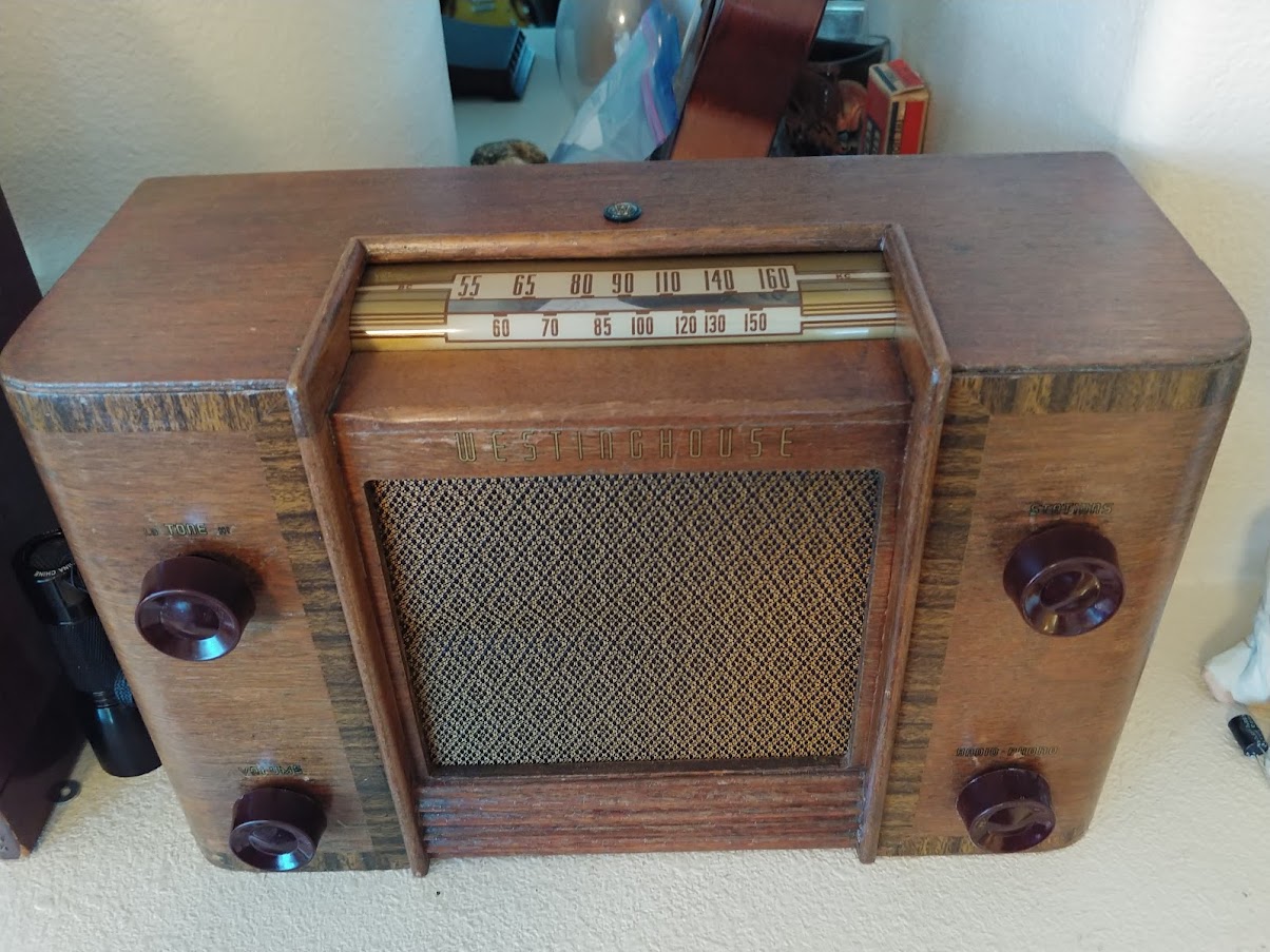
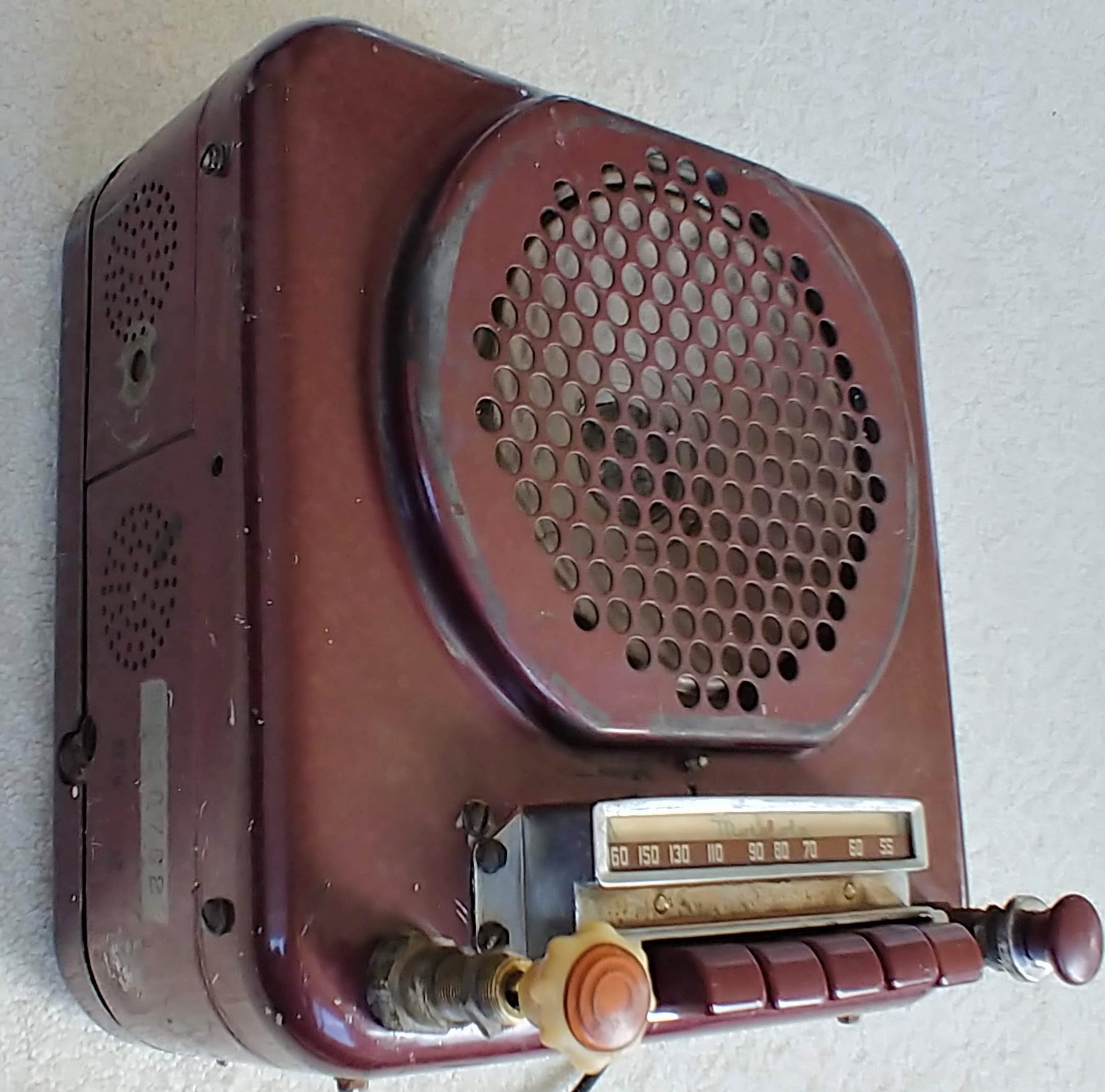
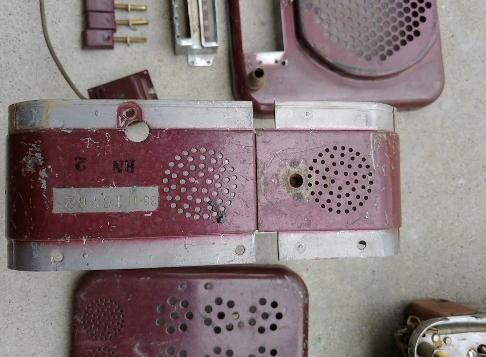
The 38-0 radio in this post has the lighting bolt logo on the back of the metal case (pic below). But on the dial face it has the logo from 1946. That would imply that this radio could not be earlier than the 1946 logo and should not have been in a 1941 Olds as the schematic indicates. But further study shows that Olds had a radio with a tuner on top of the speaker in 1946 and later. So maybe not in Olds or maybe the logo dating is inaccurate.


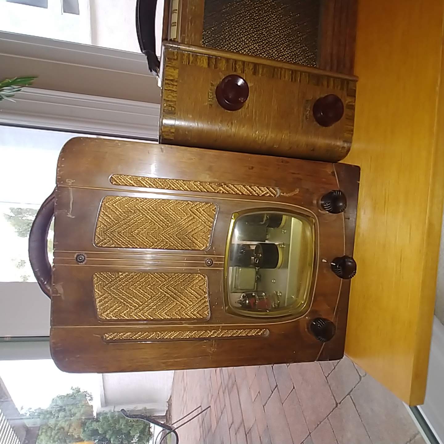
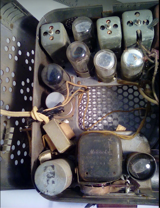
As found Radio and first Disassembly
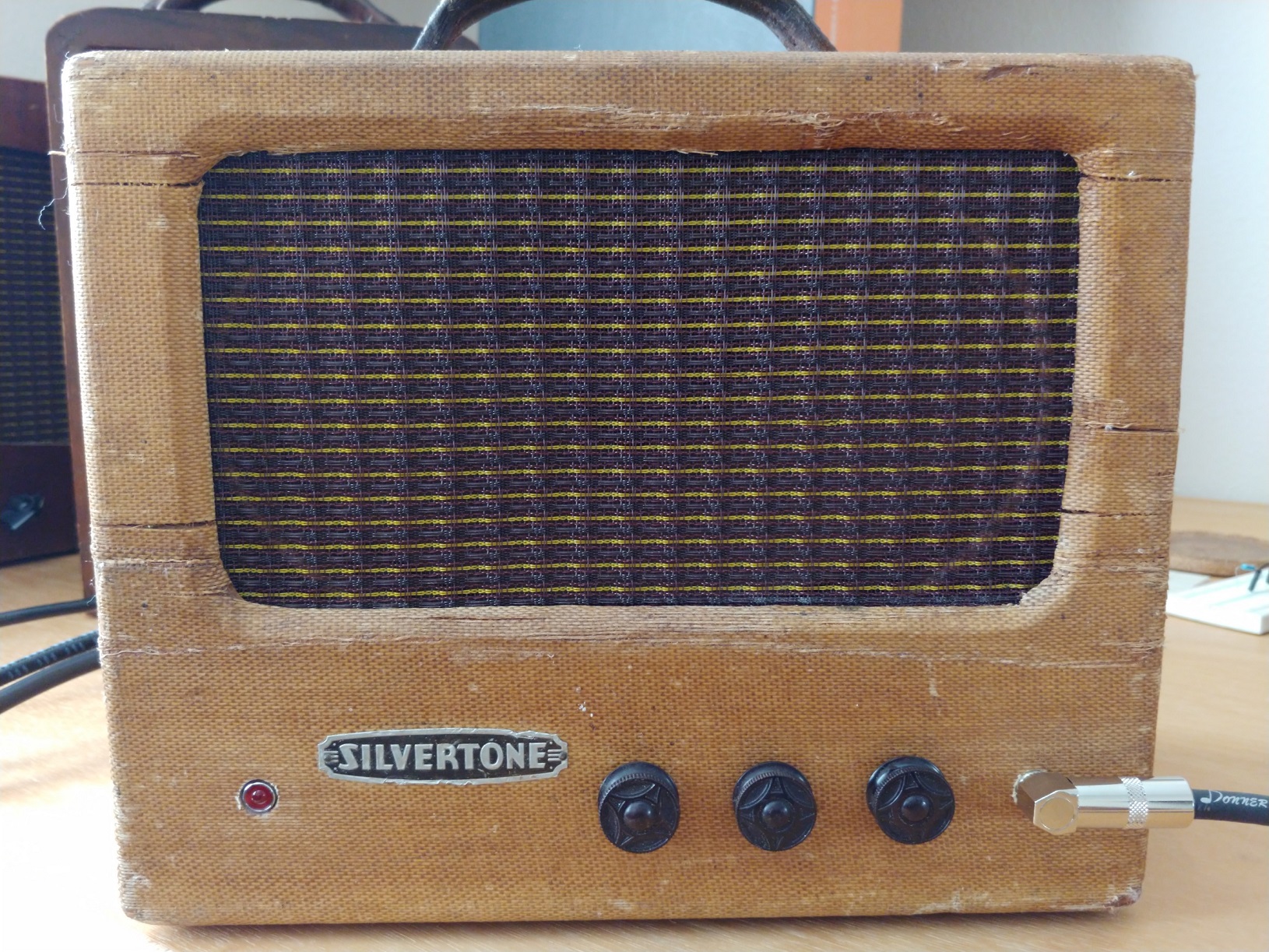
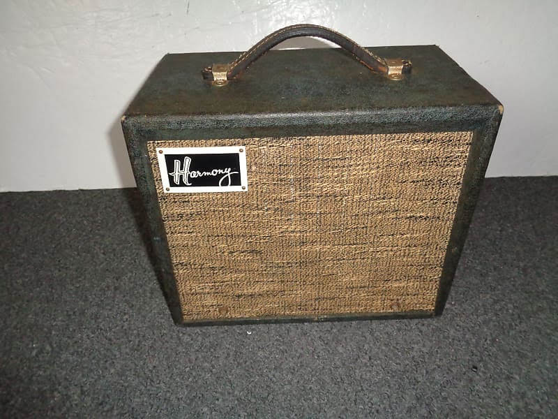
When originally purchased this radio did not have its original speaker and was destined to become a guitar amp. But it turned out that this radio was extremely rare and very few examples of it existed. So it was decided to see if an original speaker (or close) could be found and then to decide to restore or repurpose.
Unfortunately the original speaker was even more rare than the radio. But as luck (or fate) would have it. An exact replacement speaker was found online and purchased, It turns out this decision was to lead to a detailed restoration with many individual parts to be fabricated or repaired.


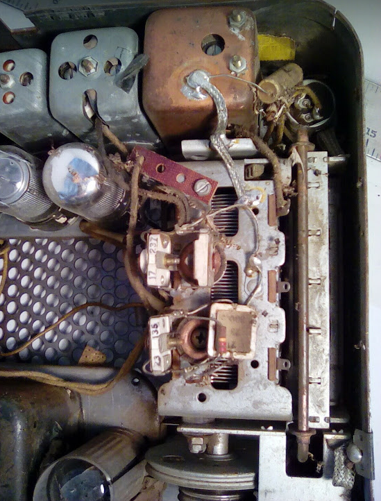


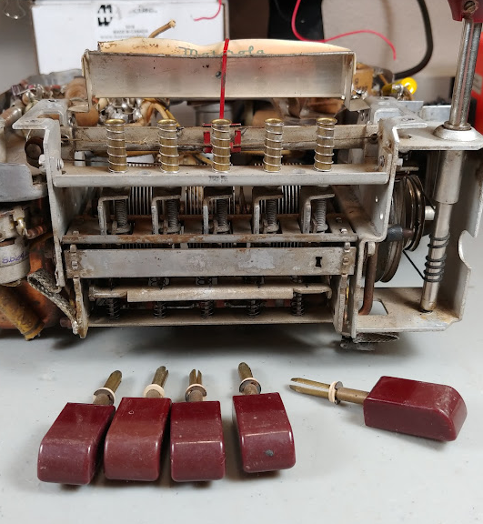
This radio adjusts the pushbutton settings manually. Never ran into this before, But figured it out as follows:
1) pull the pushbutton all the way out
2) move the dial knob to where you want it
3) insert screwdriver into push button hole and loosen the screw inside (this allows a cam to move)
4) push the screwdriver in until it stops, tighten the screw (to lock the cam against the tuning bar)
5) replace the pushbutton
very simple and ingenious mechanism.
Just need to carry a screwdriver in your car...

Schematic
As with all DC car radios a low voltage DC must be stepped up to HV. To accomplish this the DC must be converted to AC through the vibrator which is then run through the HV power transformer to get about 400vac on the secondary. This is then

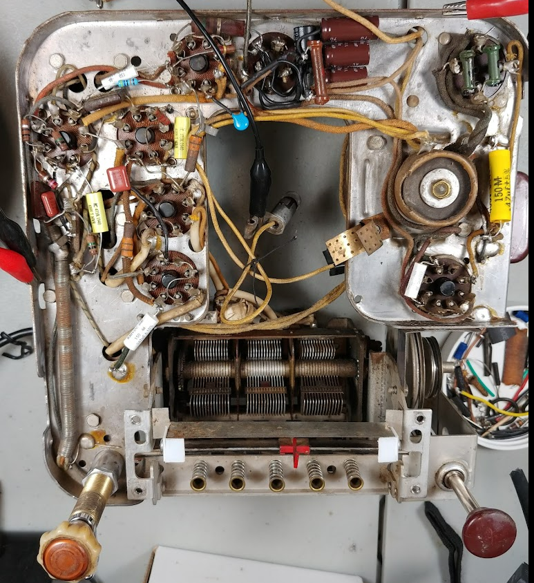
Repairs
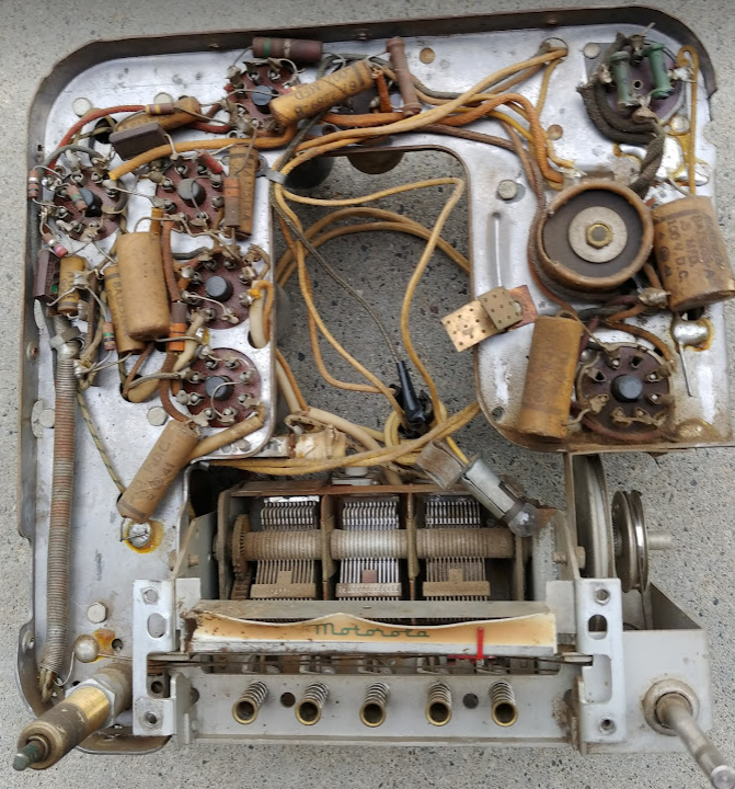
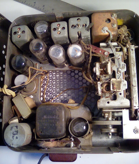
The radio needed significant component replacement and repair. All the original capacitors were replaced with modern equivalents. The big challenge was to combine the filter caps into a unit that could be installed without removing the original can. The filter unit was installed next to the rectifier in the top of the photo shown below.


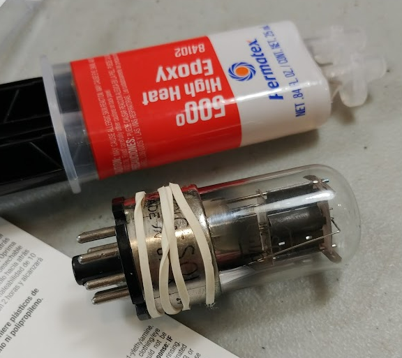
Tube Repair
The tubes were old and some needed to have their bases reglued with high temperature epoxy. THis process worked perfectly and all the tubes function well under load.

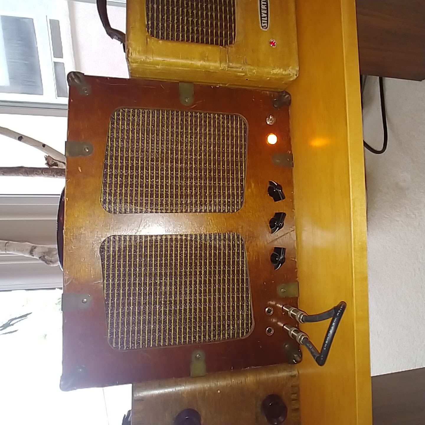
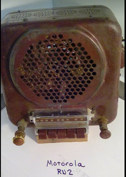
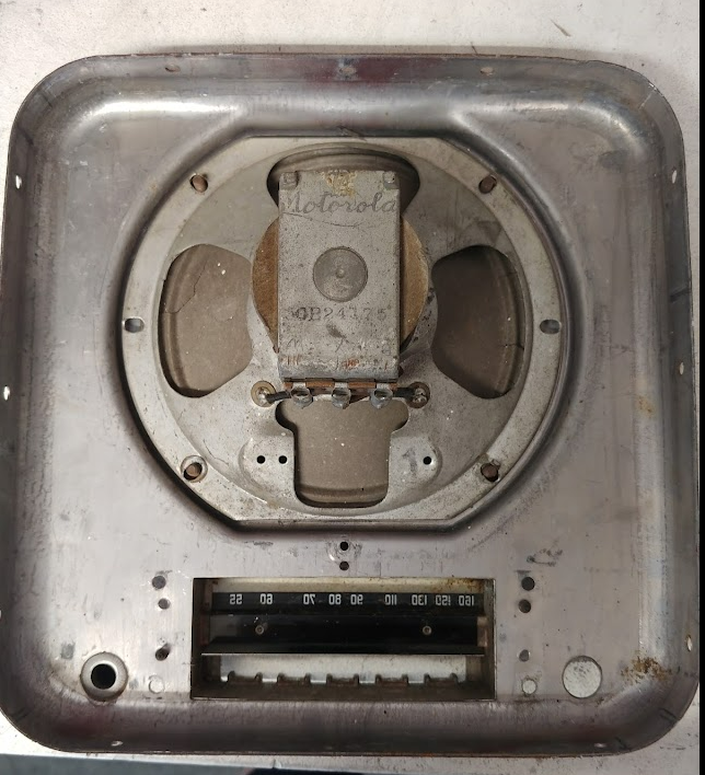
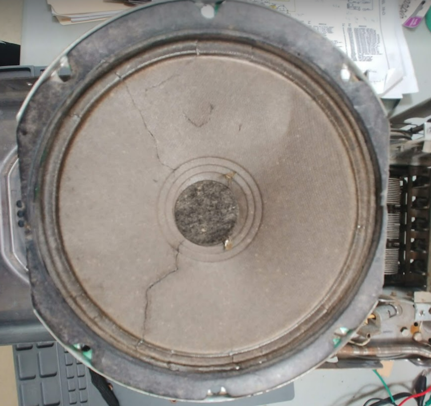
Speaker Repair
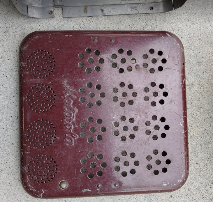
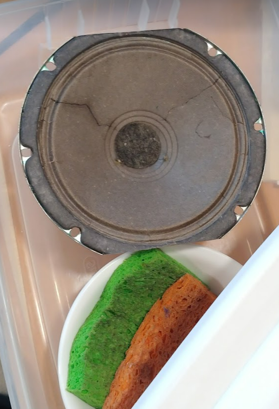
This radio came to the shop without a speaker and was originally going to be repurposed as a guitar amplifier. But as it was studied, it turned out the radio was extremely rare and so a search for an original speaker was conducted. Was like finding “hens teeth'' as it was very rare. As luck would have it, an exact speaker was found on ebay and repaired to fit the radio. The speaker needed to have one side cut to fit the opening profile of the cabinet. Also the cracks in the cone needed to be repaired with “Tacky” Glue. Now it plays good as new and it is fully original. This is shown below.
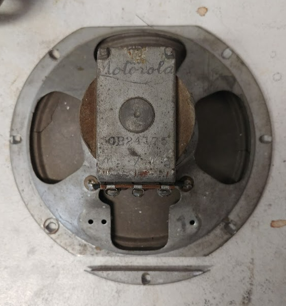

In addition, the speaker paper cone was moisturized in a sealed container with a bowl of wet sponges. The sponges were kept separate and are just for introducing moisture back into the fragile speaker paper.
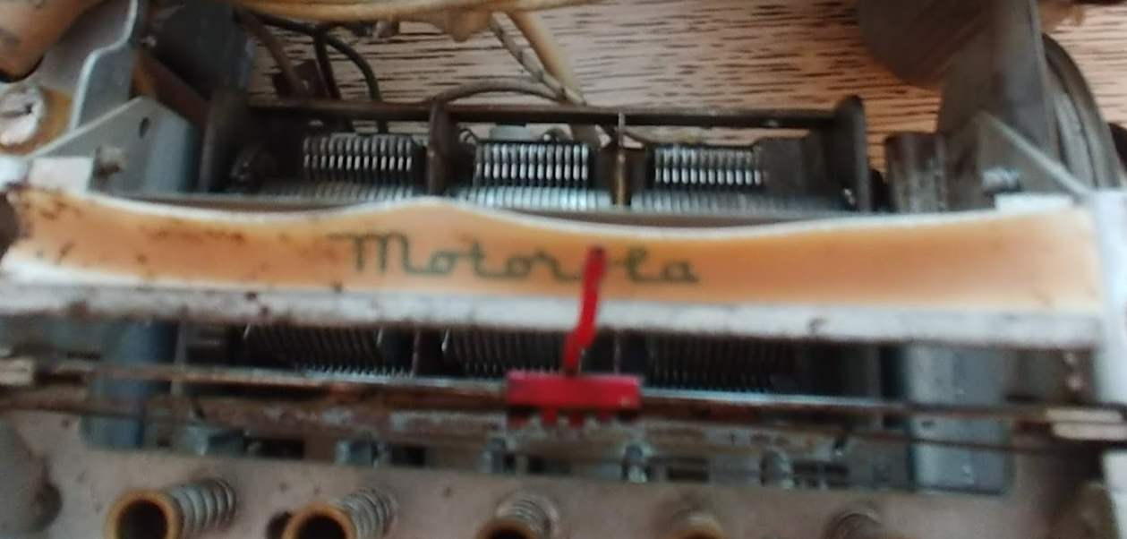
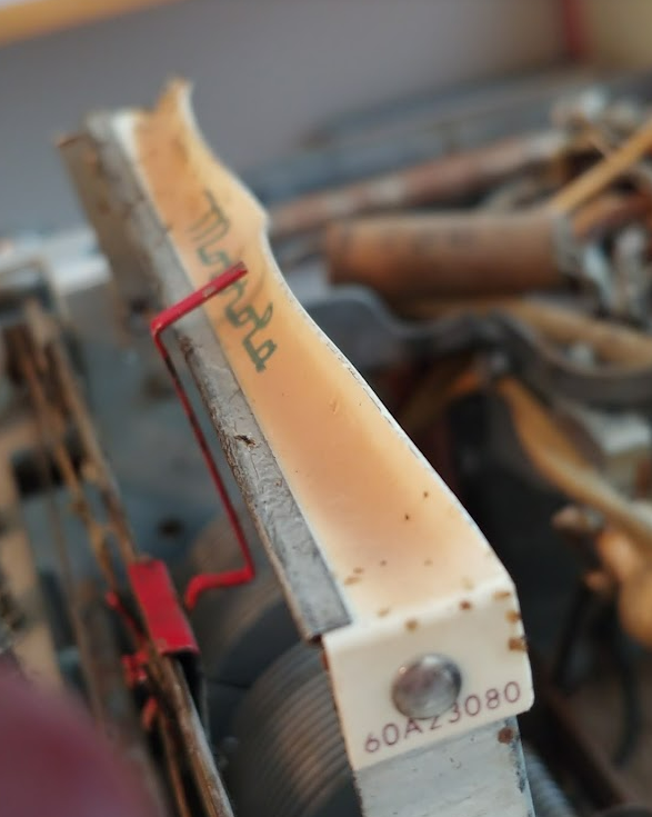
Repair the Dial Logo Platen
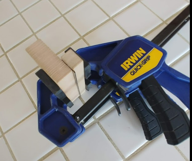
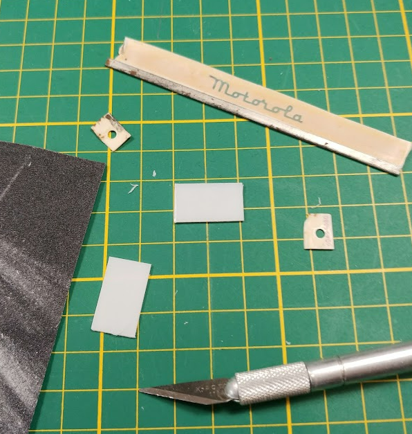
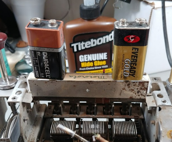
The dial face platen was badly warped and needed to be straightened. This was accomplished by soaking the platen in hot water to soften it, then clamping it between wood blocks while it dried. Result was a perfectly straight dial face. The attachment points of the platen were broken and needed to be fabricated from an equivalent material and then glued in place. The result is a flat platen that displays very well.


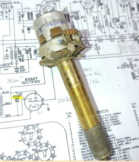
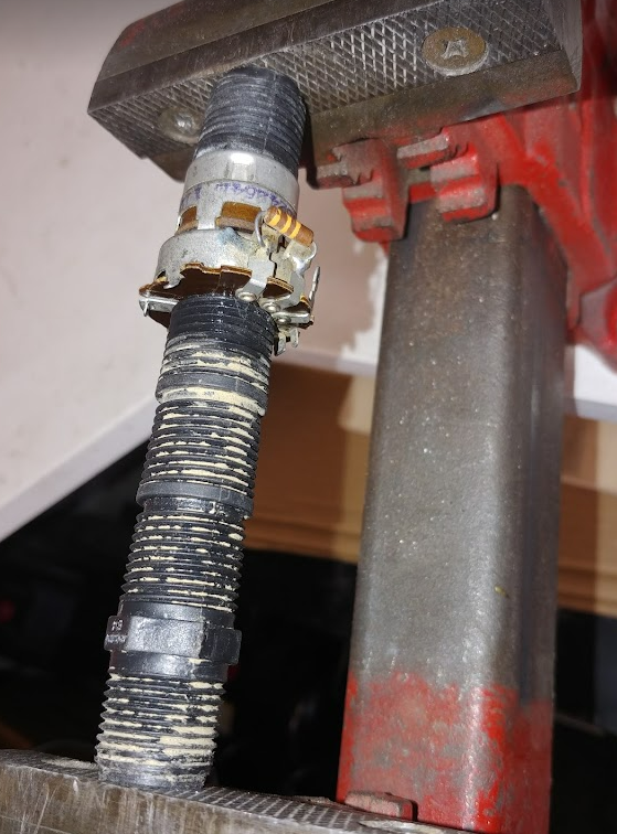
Repair the Volume Pot
The volume pot had a cracked fiber plate, and while this probably would still function, it was decided to glue and clamp it flat. This was accomplished with a small landscape pipe “cawl” that fit over the long shaft and the connectors. The assembly was clamped in a bench vice. The result was a flat fiber plate that fit in the cabinet very well.

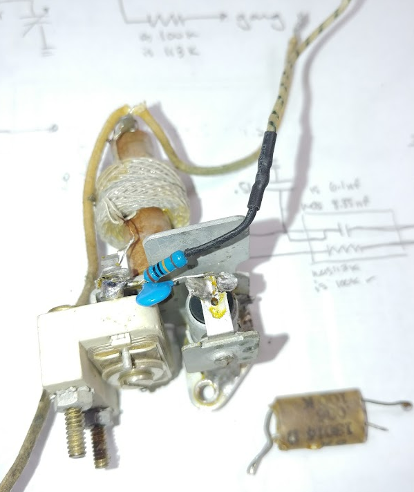
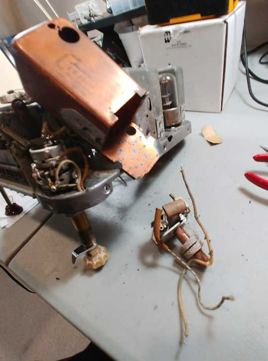
Repair the IF Transformer
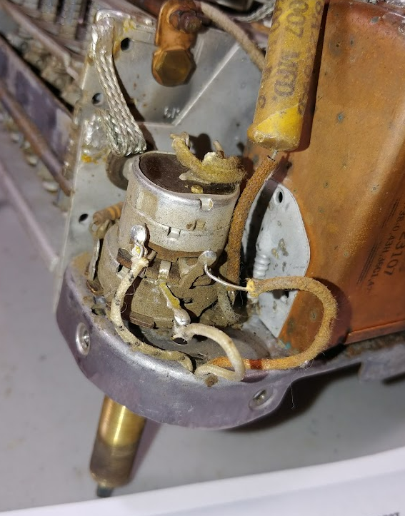
The IF transformer needed to have its caps replaced and as well as repair of a cracked ceramic that often affects performance. To access the IF transformer it was necessary to open the copper can that housed the IF transformer. To repair the ceramic glue was applied and clamped in place

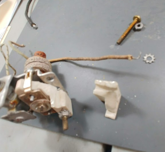

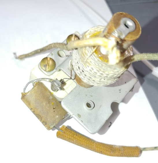
Usual component that included a capacitor and a resistor in the same package.