.jpg)
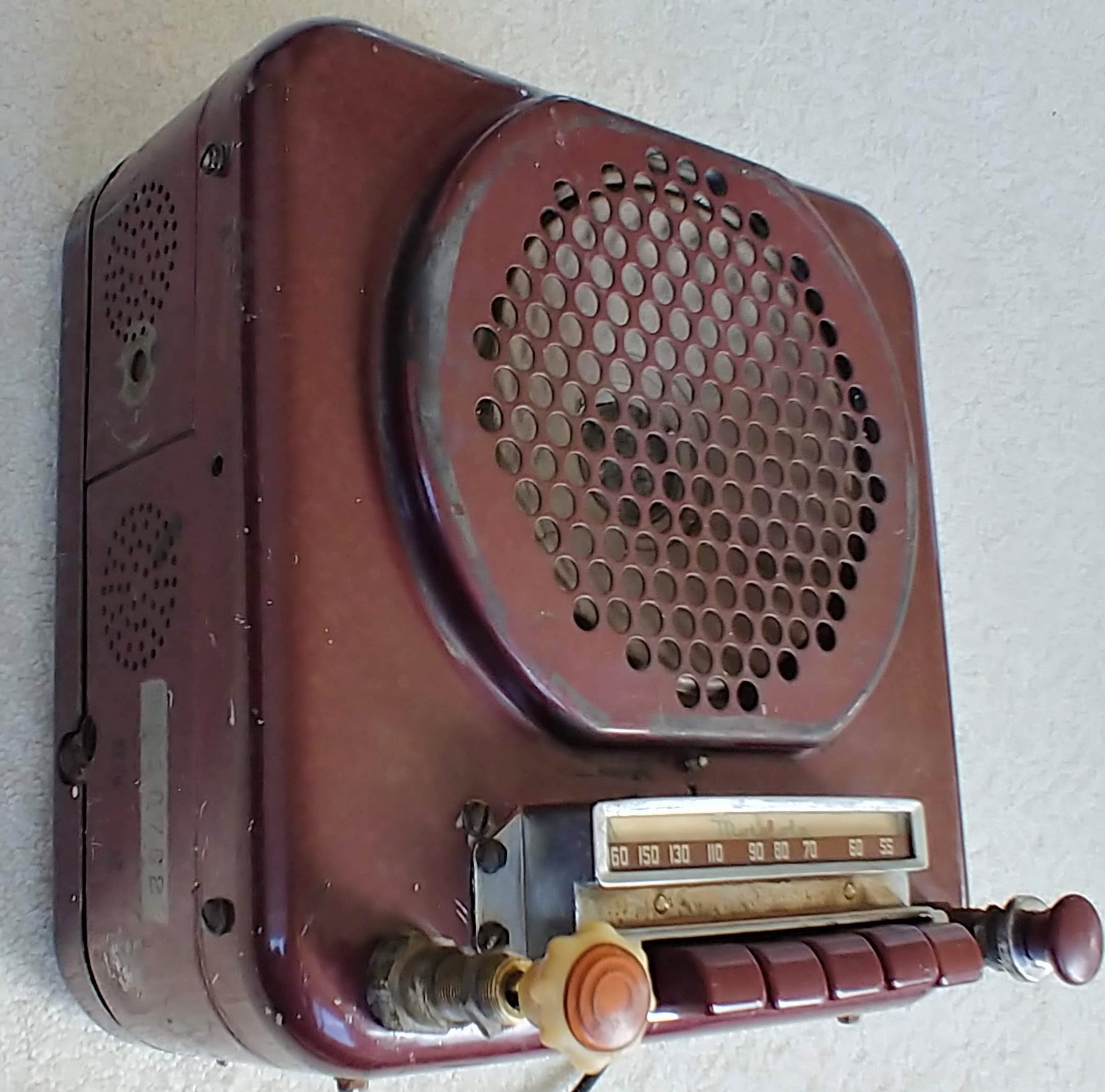
Prew42
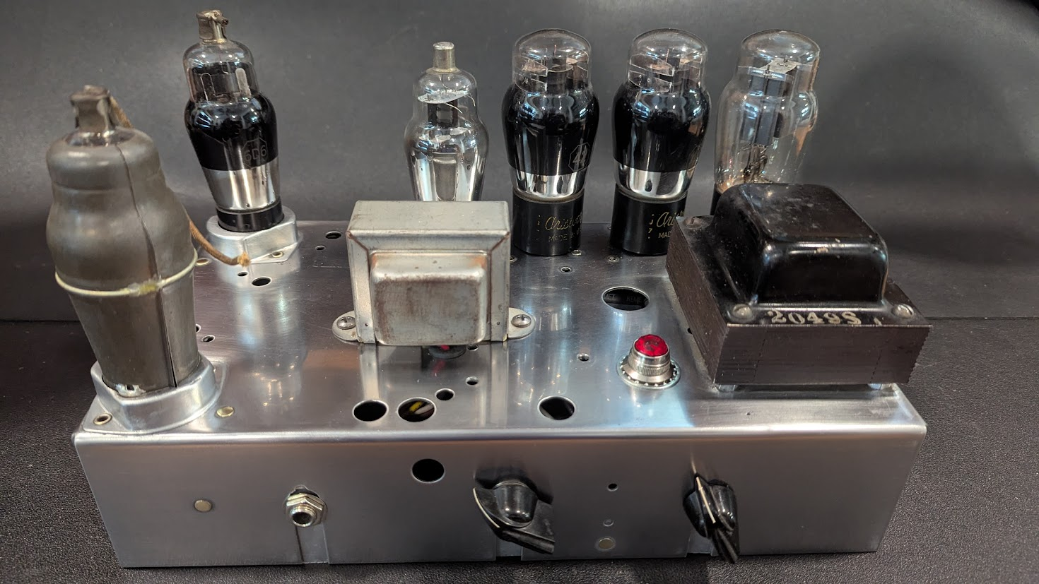
The objective is to build a safe and great sounding pre-war (WW2) guitar amp using as much technology from the day. This guitar amp will be based on a 1936 Aetna 19w66a tombstone radio. Only the loaded chassis was available. In another project, a complete Aetna radio was restored (https://stillampd.com/aetna-19a66w-tombstone-radio). The available chassis sported a great tube complement so it was thought that it might make for an excellent guitar amp. The design has evolved but in essence it will be a push pull amplifier using the original No42 pentode tubes. The Phase Inverter will use the original No75 single triode tube configured as a cathodyne phase inverter, The preamp will use the original 6D6 pentode. A second preamp stage will be added by consuming the original 6A7 socket with a rare 6D7 that is metal clad like an Iron Maiden. The original power transformer will be used along with the original No80 full wave rectifier tube. Most other parts of the radio are removed for use in other projects.
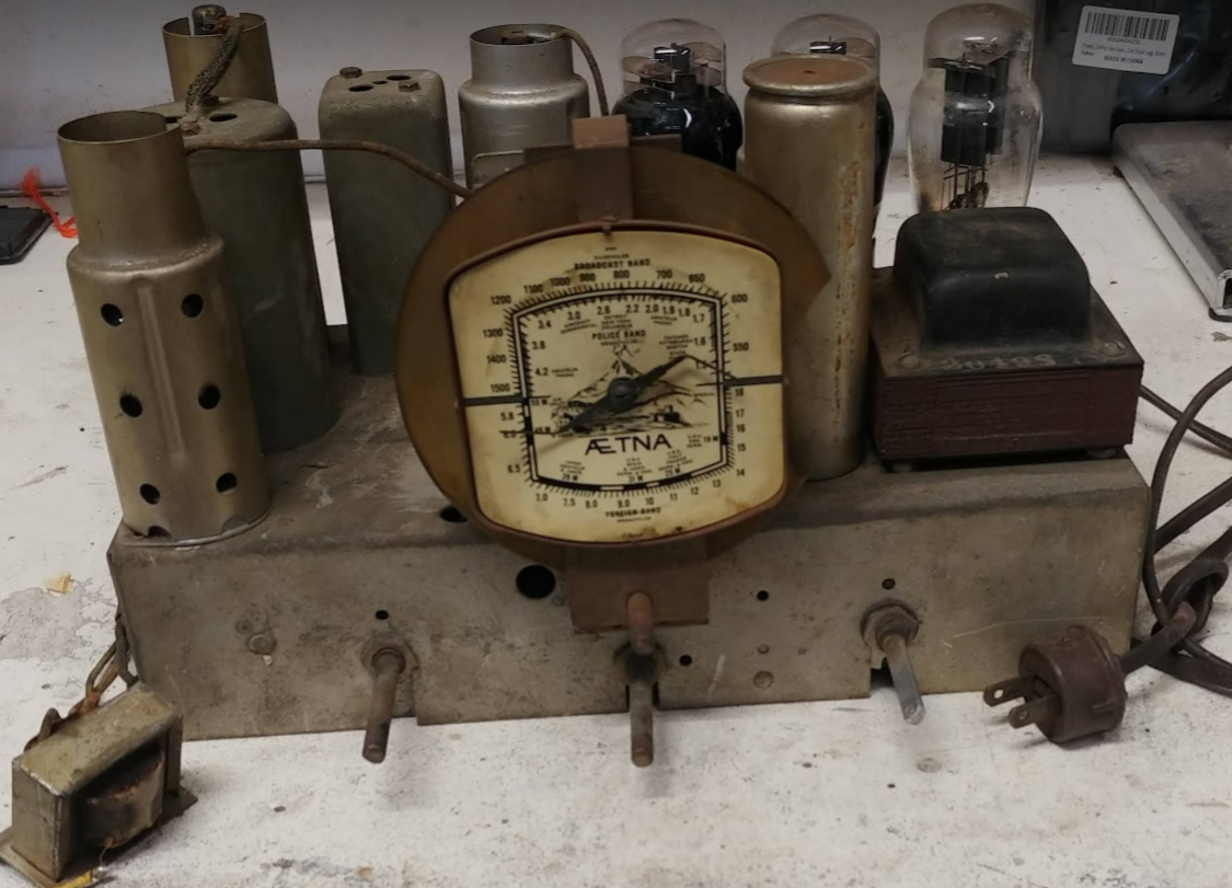
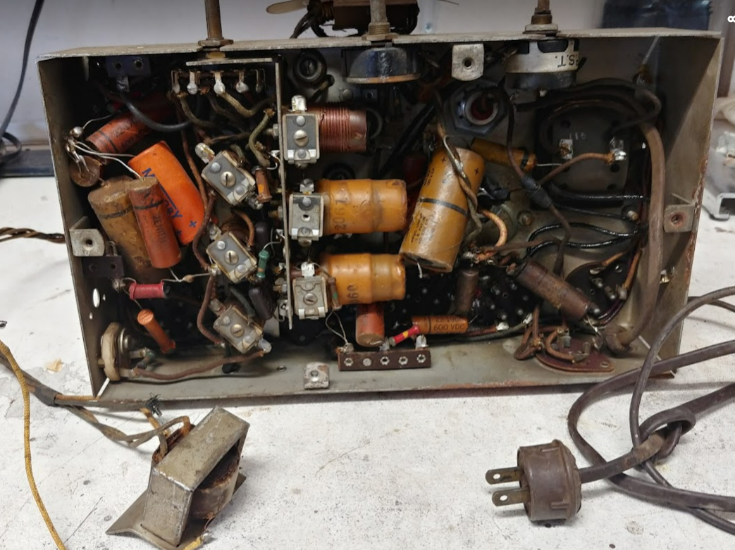
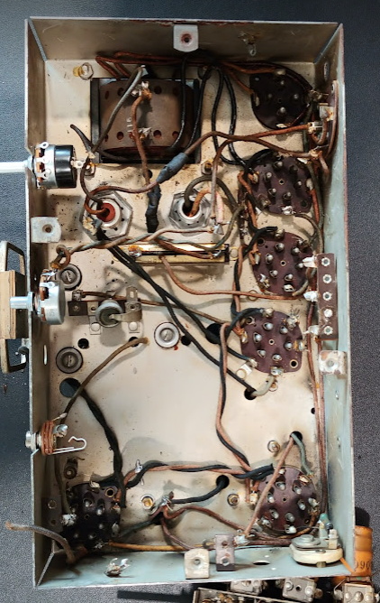
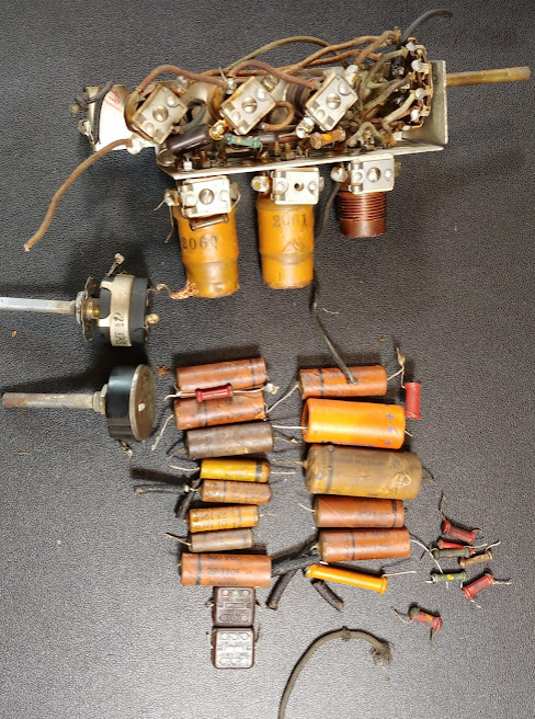
The original chassis is very crowded on the top and inside. So many of the radio components that are not used will be removed.
Restoring the Chassis
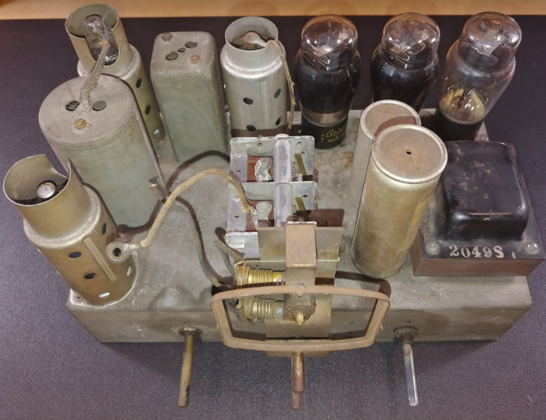
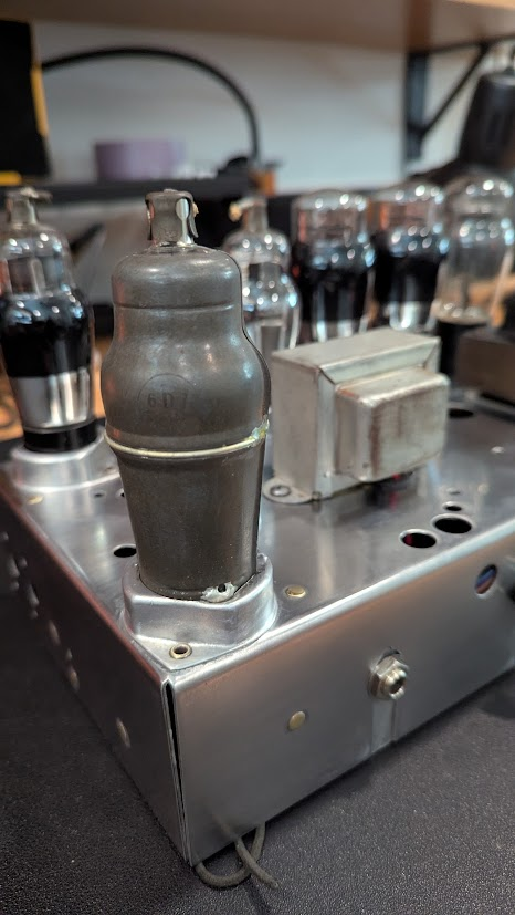
I typically love chassis patina and just leave it. But in this build I decided to build a cabinet (below) which seemed to clash with the old chassis patina. So I decided to restore the chassis. To do this I removed most parts, taped the riveted sockets, wet-sand by hand with progressively finer grits (sanding sponges worked really well), then hand polished with Mothers polish. I did not add any other protection (maybe I should). Hoping that the chassis and cabinet age well together. I left the inside patina as it was.
Prewar Tubeset
Surprisingly, the tubes available in the Aetna radio are quite similar to other tubes that are commonly used in guitar amplifiers which should make the circuit design much easier. The No 42 pentode tube is very similar to the 6V6, the No75 triode tube is similar to the 12AX7, except for the dual diodes in the 75 (that will not be used here) and that the 12AX7 has dual triodes. The 6D6 pentode is similar to the 6SJ7. Some of the numbers are noted below.
Based on the research provided by Radio Museum, the 6V6 octal tube, very common in many modern day guitar amplifiers, is a successor tube to the 6F6 tube which is the successor tube to the 42 being used in Prew42.
The 12AX7 is a descendent of the 75 being used in the Prew42 amplifier. The Type 75 is a triode-diode tube dating back to 1930. The 75 evolved into the 6SQ7 which is an octal-based double-diode triode commonly used in AM radios. The 6SQ7 evolved into the 6AV6 which is a miniature version of the 6SQ7, repackaged with a single cathode. The 12AX7, a twin triode, is essentially composed of two triodes from the 6AV6.
A more thorough tube comparison below.
* Assuming max plate current, but more likely around 90 in typical operation
6D7 Iron Maiden
The 6D7 tube with its metal clad body looks like the iron maiden medevil torture device. In the case of the 6D7 it is selected as a second stage because it was consistent with desirable pentode characteristic and would fit the tube slot vacated by the 6A7 pentagrid that Could not be designed into this guitar amp (as hard as I tried me and the various forums could not determine a use for this tube). The 6D7 was also used in the Phirty6 amplifier as a second stage in the all pentode preamp channel. The 6D7 was a successor to the 77 tube and a predecessor to the 6J7 according to Radio Museum. Difficult to find a 6D7 datasheet so the 6J7 was used for design, Radio Museum calls the 6D7 a metalized 6C6 with a 7 pin base
Circuit Design
The Aetna radio usd the pair of 42 tubes in a parallel plate Single Ended (SE) design. It was initially thought to copy this same design so as to use the SE output transformer (OT) that was available in the radio. However, a single 42 tube wants to see a resistive load of 7000 ohms and a pair would need a load of 3500 ohms (half of a single 42). The measured impedance ratio for the OT was 1457 which meant that for a parallel plate 42 would need a speaker impedance of 2.4ohms. While this could be made with a couple of 4 ohm speakers in parallel, it was decided to provide a bit more flexibility with a OT That had switchable speaker impedances. And since the OT was being replaced it was a great time to upgrade from single ended class A to push pull class AB. A company called Musical Power Supply makes a perfect OT that is 10k ohm primary (That two 42’s in push pull want to see) into a selectable 4/8/16 ohm secondary, all at 18VA which is perfect for the 42 pair as they could produce about 19 watts.
Output Design
A great little prewar amp from the 1930’s was called the Volutone model 5. The power tube output stage will be based on this rather simple design. Shown in the schematic below. Two 42 tubes running push pull with a cathode biased approach. This design shows the screens running the same voltage as the plates. More information available at this site http://prewaramps.org/volutonemod.htm. However the Volutone 5 design has a reactive PI with the transformer center tap essentially tying the 42 grids to ground. Prew42 will have a resistive input to the 42 tubes and so it will need grid leak resistors tying the grids to ground. It is also decided to add grid stops in the style of the 5E3 (Fender Deluxe).
Biasing the 42
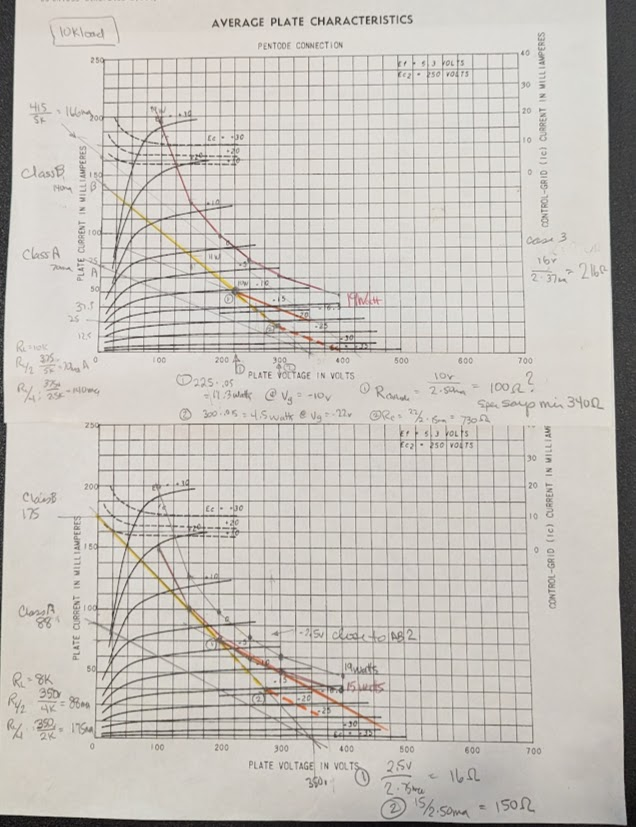
Not much is written online for the design of the 42 tube in push pull amplifiers. Since this is guitar amp it is desired to operate as class AB1 somewhat in the middle of the load line. But here is where the confusion starts.
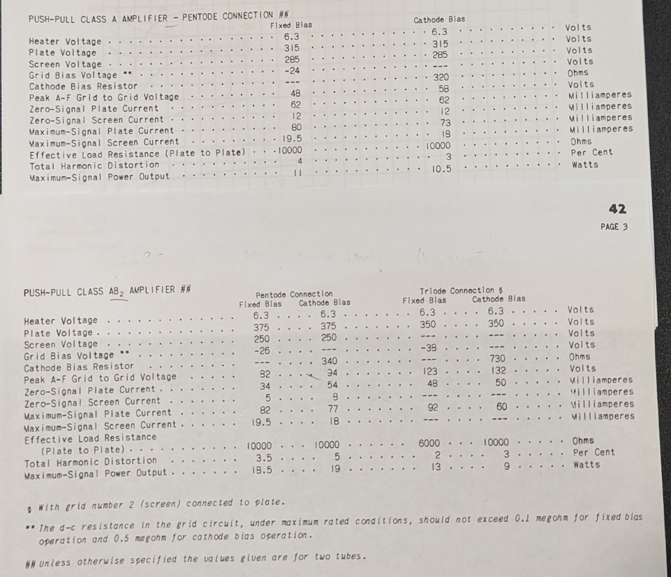
For 10k load: The 42 datasheet shows a load impedance of 10k ohms which corresponds to the class A and Class B load line in the diagram for 350v plates and 250v on the screens. If the design point 1 is used the 42 cathode resistor would be 100 ohms with an output power of about 11.3 watts. If design point 2 (closer to the datasheet grid voltage of -26v) is used then the 42 cathode resistor would be 867 ohms at an output power of about 7.5 watts.
For 8k load: The Output Transformer for this design has an option for 8k ohms. The figure shows the same AB load line for 8k load which if the operating point in the middle is selected then a grid voltage of -2.5v would require a cathode resistor of 16 ohms at about 15 watts. If the design point is a grid voltage of -15v then a cathode resistor of 150 ohms is needed with an output power of 10 watts.
Phase Inverter Design
Typically Phase inverters use two triodes in long tail designs but finding a dual triode was difficult, the 6A6 was a possibility but it required a lot more heater and plate current that what might be available from the existing power transformer. Since there already was a single triode No75 tube available it was considered to design a cathodyne phase inverter that used a single triode. http://www.valvewizard.co.uk/cathodyne.html
The Fender AA1164 Blackface Princeton uses a 12AX7 as a Cathodyne that drives a pair of 6V6’s. Since the 75 and the 12AX7 are very similar (as well as the 42 and 6V6) it was considered to use the Cathodyne from the AA1164. This is shown in the schematic below. More information and discussion available at this site https://robrobinette.com/AA1164_Princeton_Reverb.htm
Second Channel
The radio chassis planned for use has an extra 6A7 tube that wasn't planned in the guitar amp. https://frank.pocnet.net/sheets/127/6/6A7.pdf
Since the 6A7 is a Heptode (7 element) or Pentagrid (5 grid) tube it would take some research to determine if this could be designed as a preamp tube. It was thought that maybe the 6A7 could be wired as a pentode. This approach did not work out so the 6A7 tube was abandoned.
Preamp Design
See this excellent writeup of using pentode as preamp stage http://www.valvewizard.co.uk/pentode.html
See post #6 at this like for 6D6 used as preamp https://el34world.com/Forum/index.php?topic=24476.msg263210#msg263210
Power Supply
The power supply will use the existing Aetna power transformer (PT) and full wave rectifier tube #80.

Layout
The layout of the amp follows the radio in that the existing tube sockets will be used as well as the power transformer. Since a new output transformer will be used, it will be mounted inside the chassis rather than on top since it is new and would contrast with the existing patina.
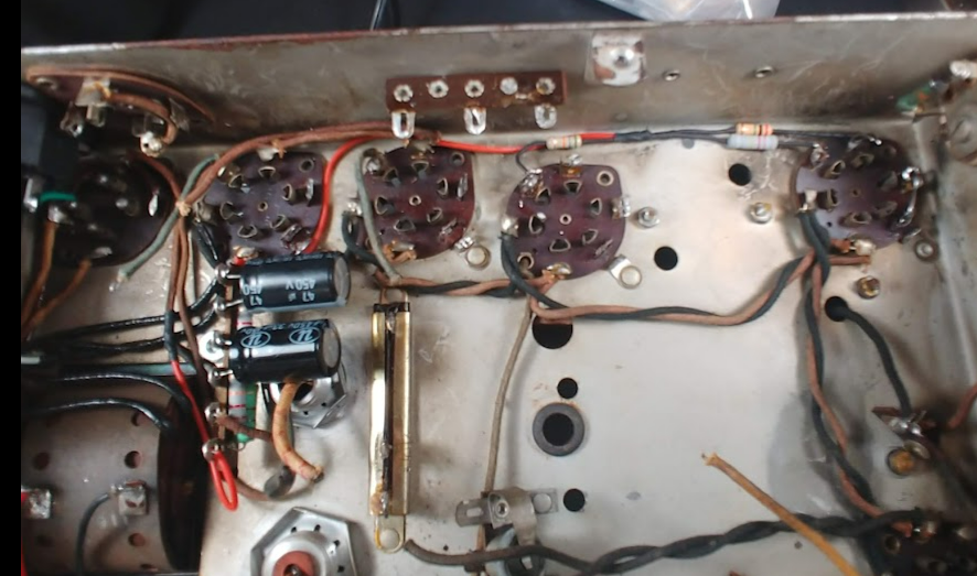
Lots of room after old radio components removed
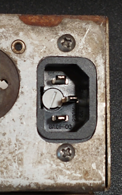
The radio band selector switch will be removed and a guitar input jack installed in its place. The speaker jack will be mounted on the rear of the chassis along with the AC receptacle.
AC wired. All original heater wiring will be retained.

Power supply filter fabricated and installed. HV DC applied to preamp and phase inverter plates. Original radio cathode to chassis ground connections removed in preparation for cathode bias scheme of the guitar amp.
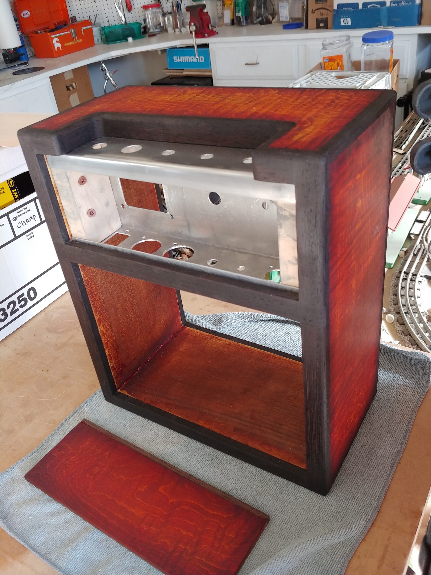
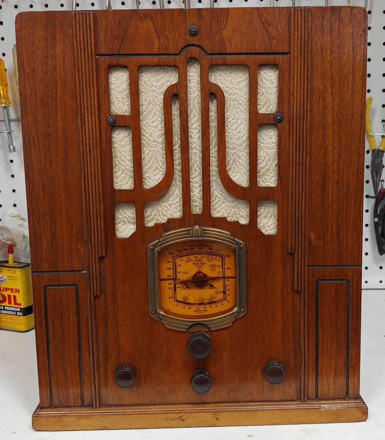
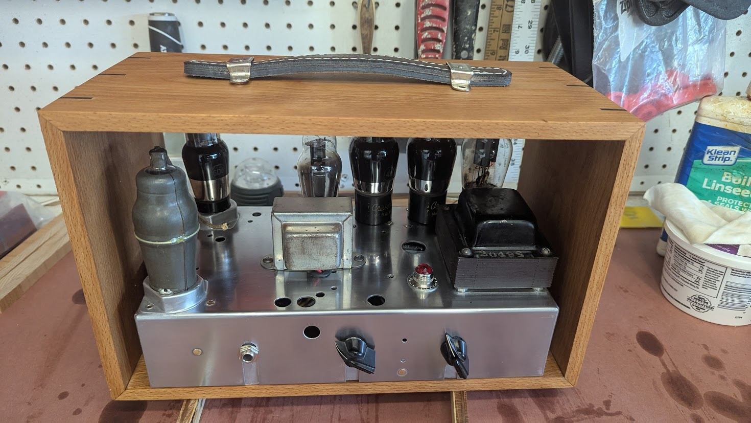
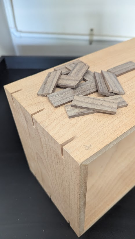
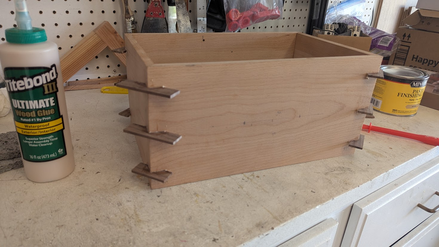
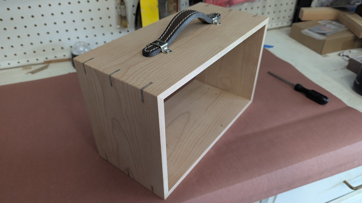
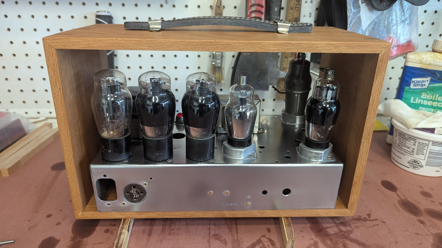
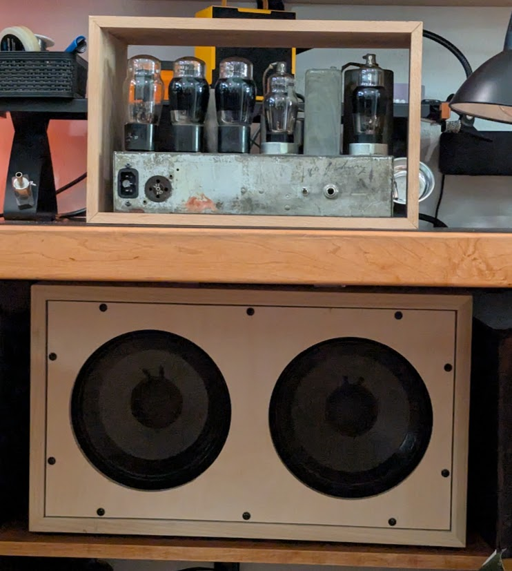
The Cabinet
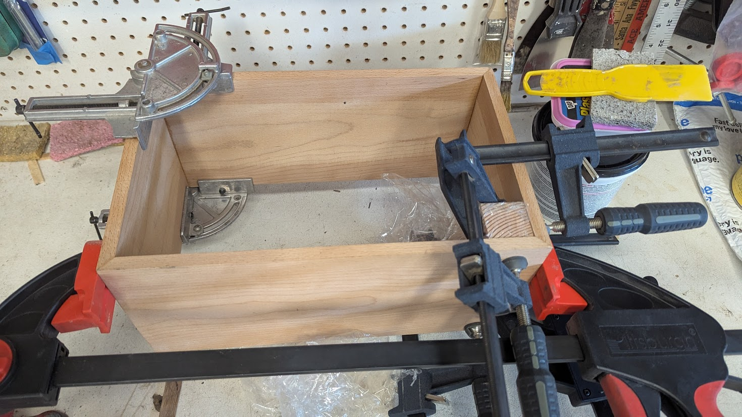
This amp will sit inside a custom beech wood cabinet with open front and rear. The miter joints are tight and will be finished with the walnut splines on each corner for additional strength and good looks. Several coats of boiled linseed oil are applied, with a light sand between coats, for a great finish look.
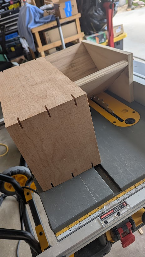
The Cabinet on the saw table and the splines are cut with the spline jig on the side, Square cut blade used.

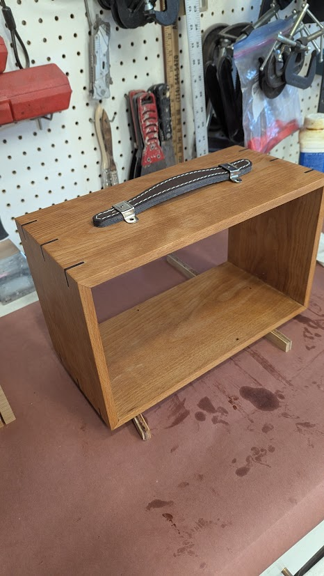
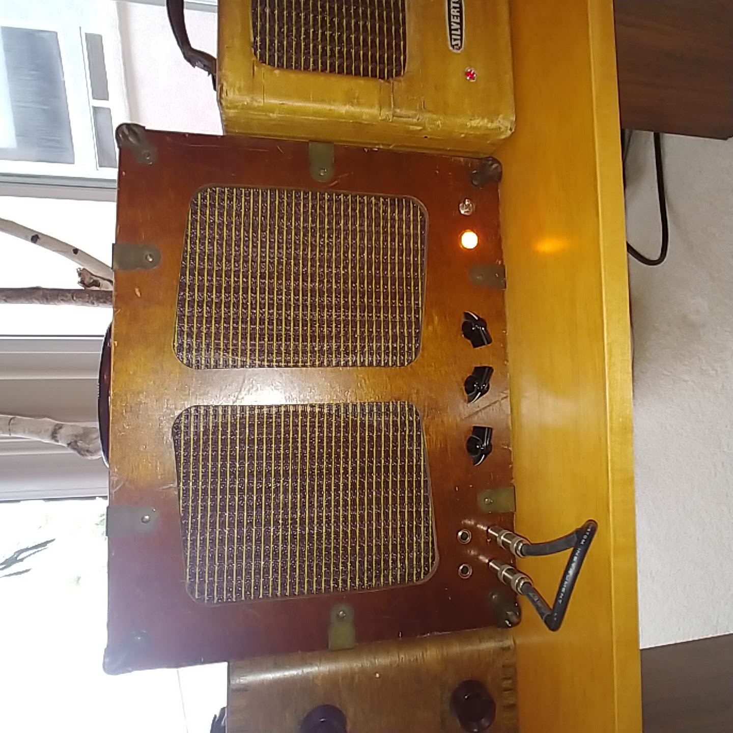
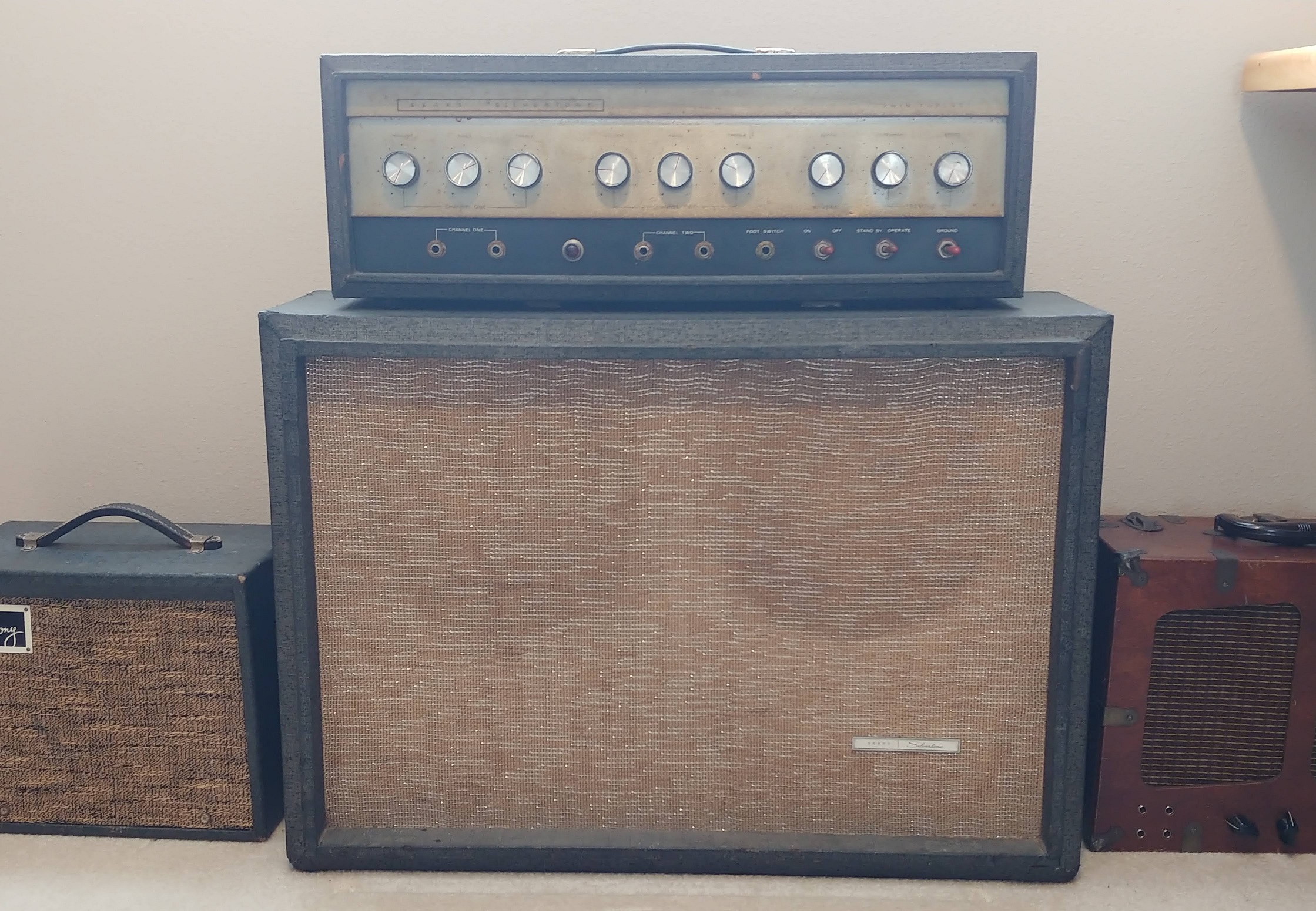
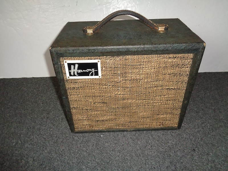
Seems a perfect head match up for the Popl210 speaker cabinet
References