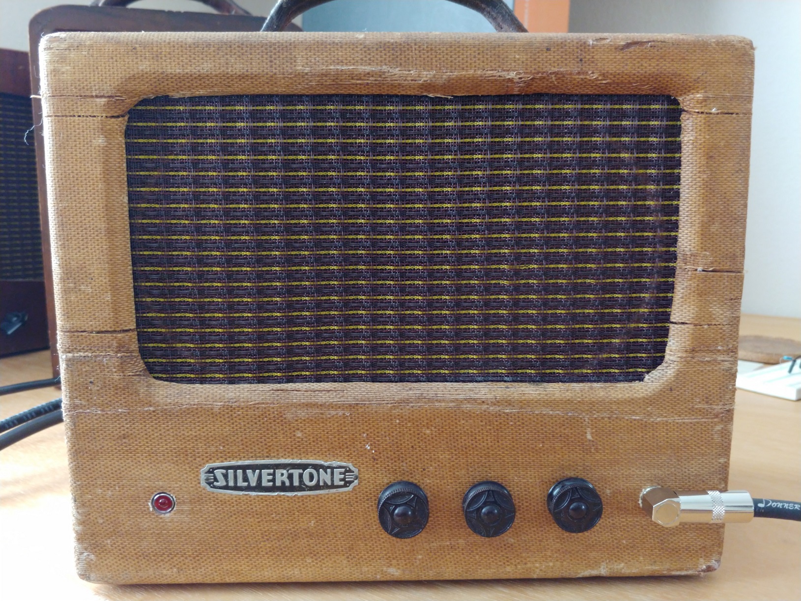
Phirty6
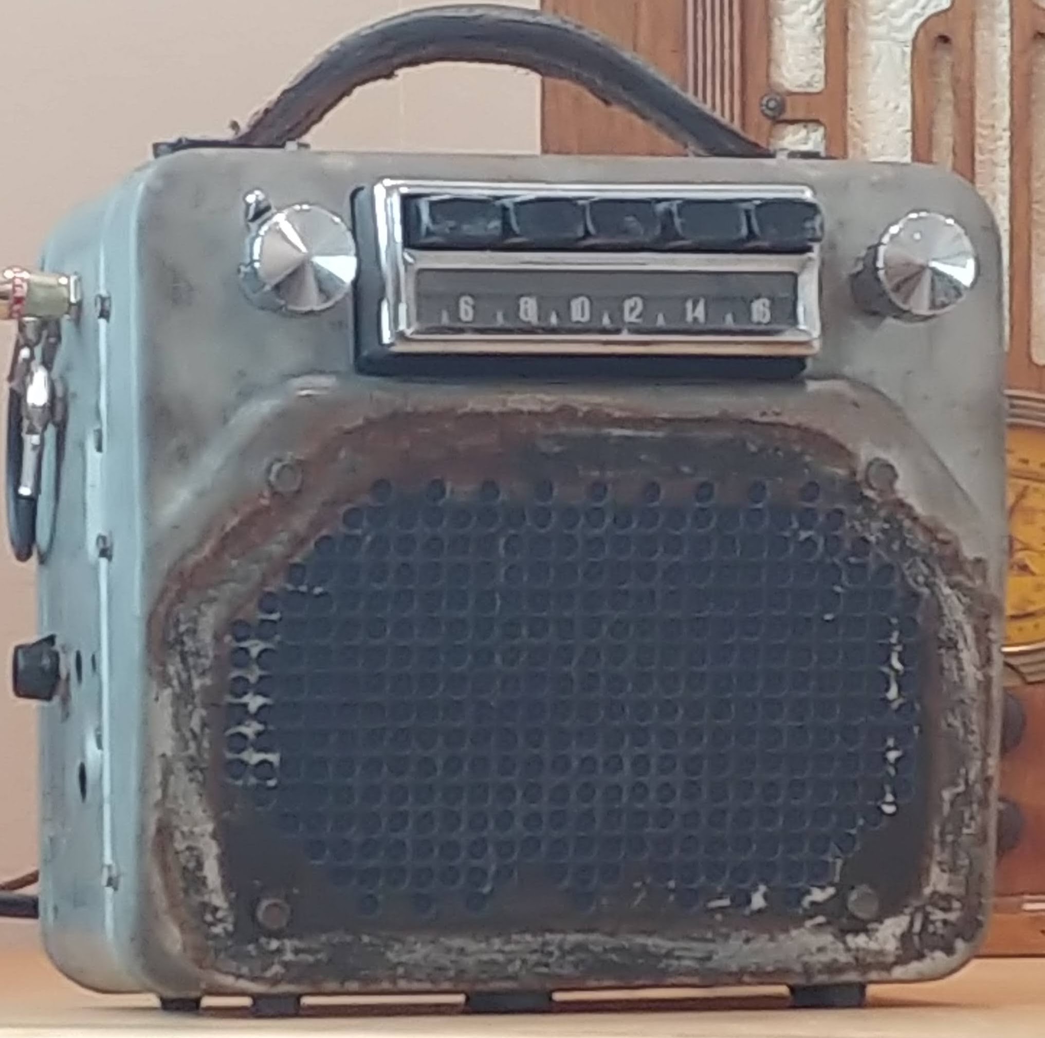
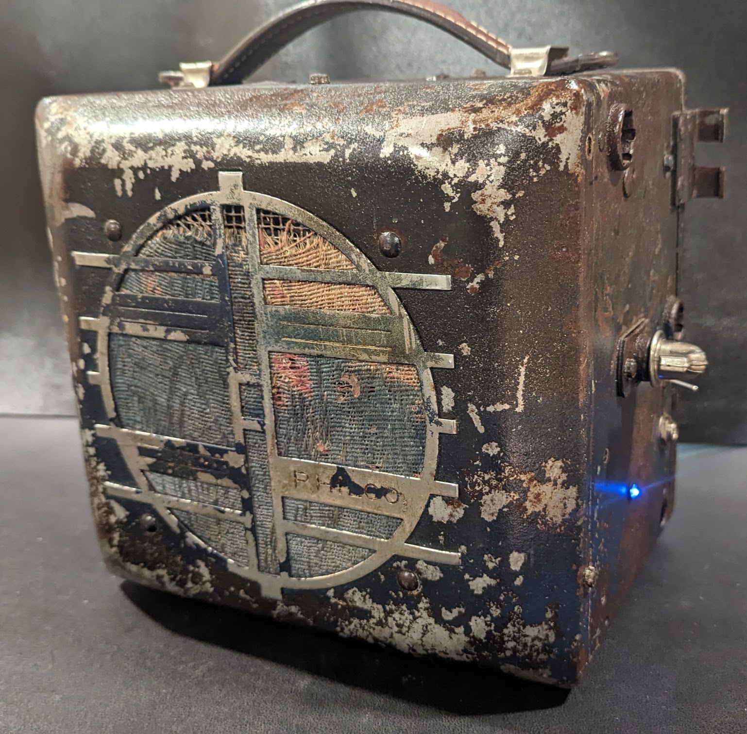
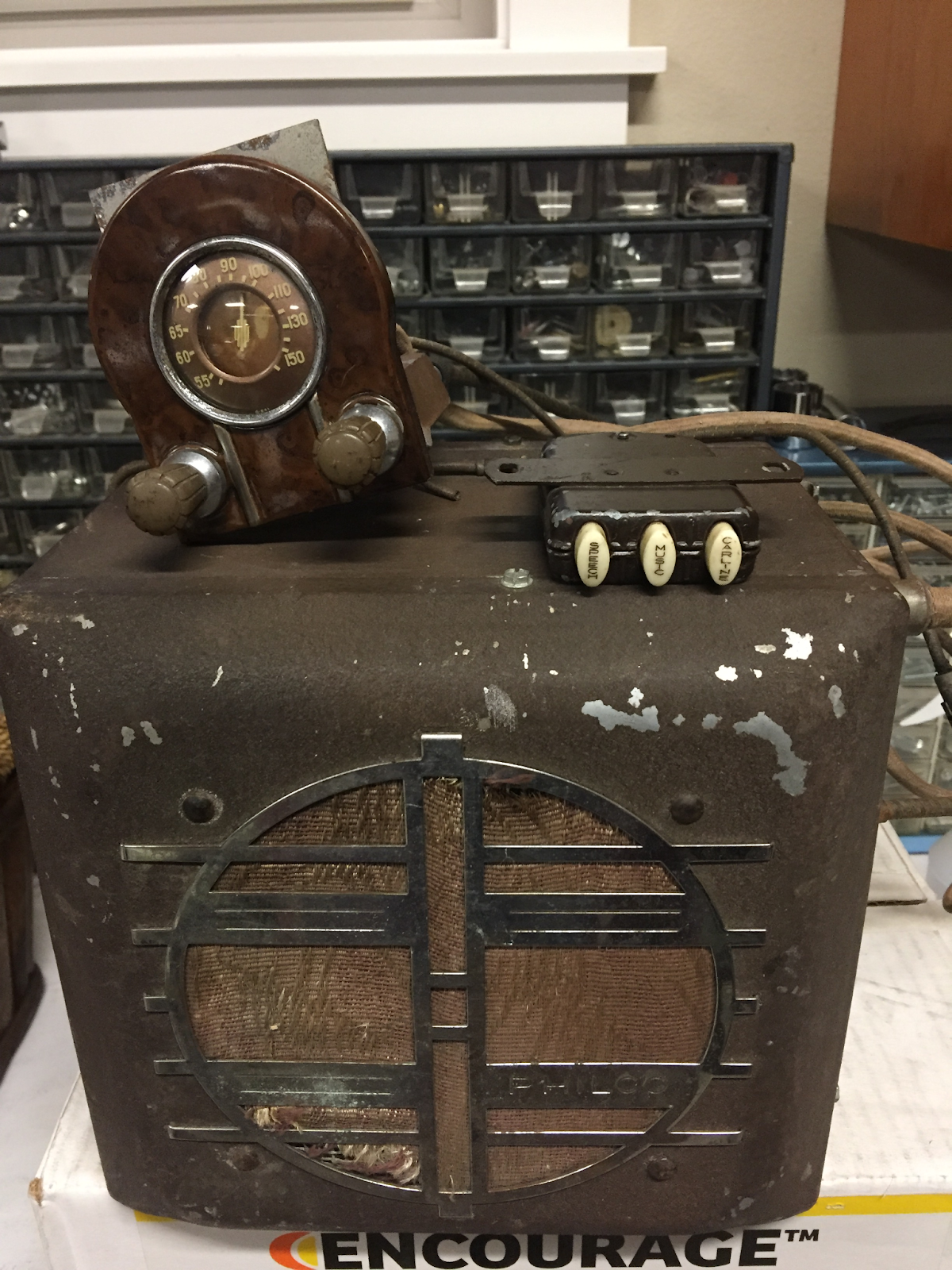
The Phirty6 guitar amp is named after the Philco 926 6v car radio and the Thirty 6 label that was painted on its face at some point in its distant past. The Phirty6 makes use of the original tubes, choke, and output transformer from the 926. A period-correct Power Transformer was added to allow the amp to be powered by 120v AC wall power. A modern 6” Eminence ceramic speaker was added. The original patina of the 926 was clear satin coated for protection. A leather handle was added to the top. A blue LED is used for pilot light and a period-correct unusual knob was used to control the volume. A switch is added near the guitar input to allow the selection between Channel 1 (triode) or Channel 2 (pentode) or both. A great sounding guitar amp that produces a solid 3-5 watts of single ended classA power. Very clean to about half volume then a great overdrive as the volume is rolled up.
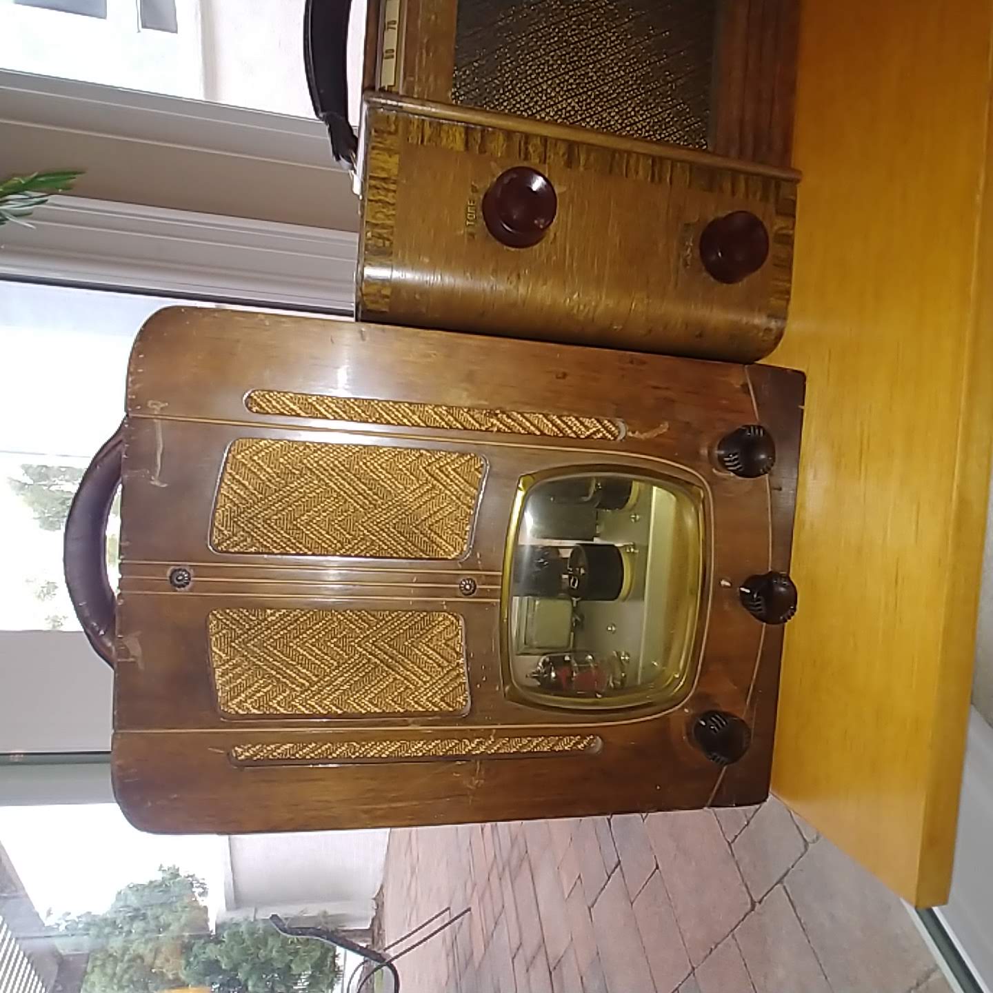
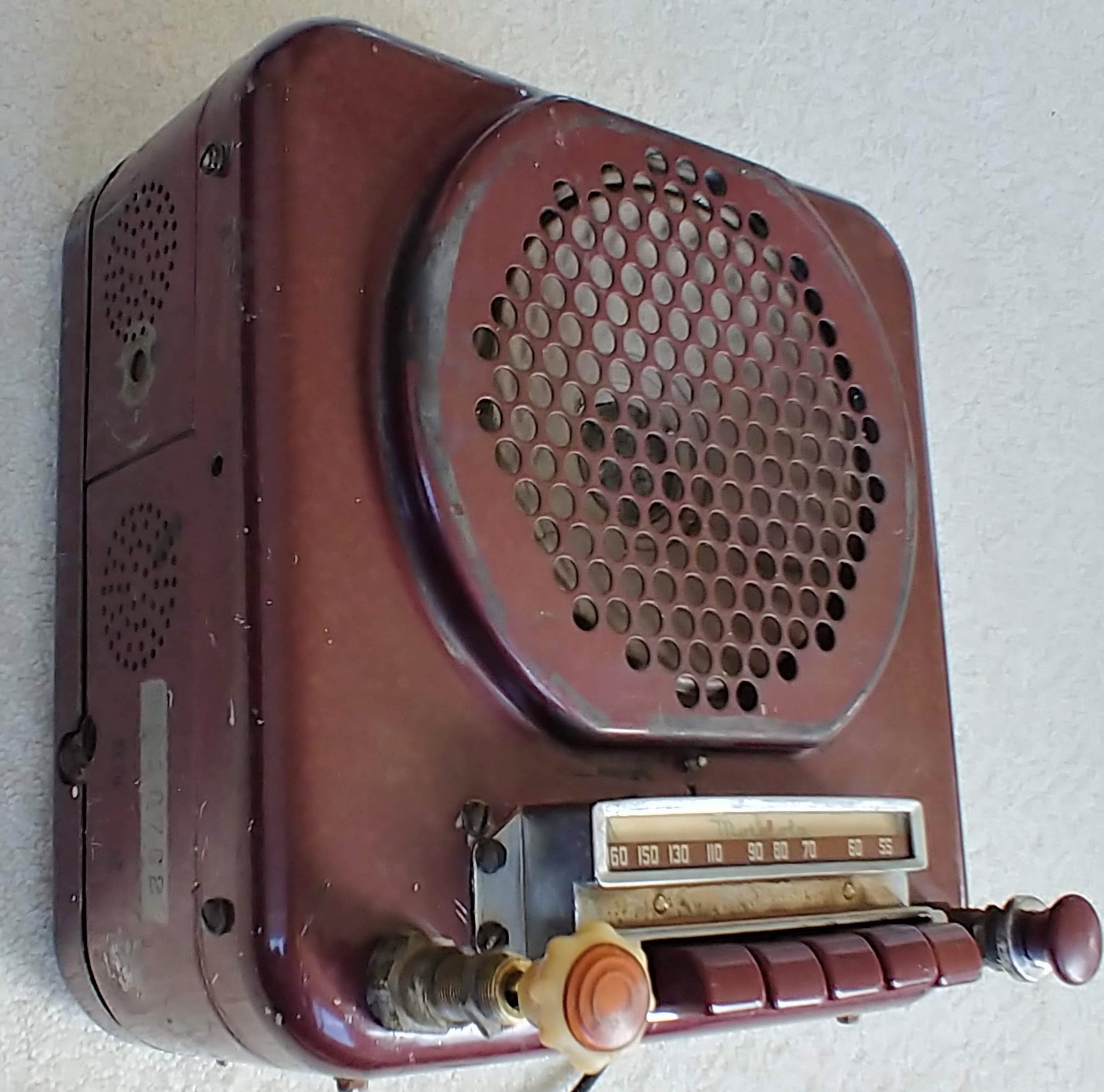
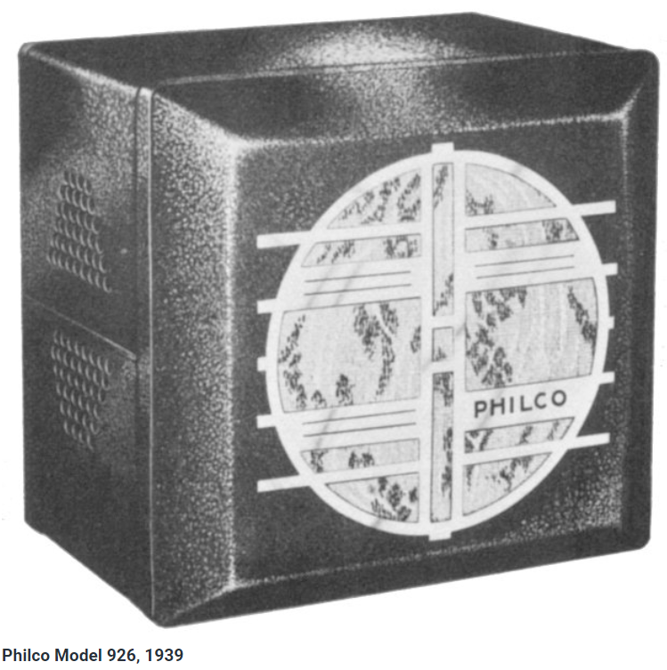
Philco 926 Radio
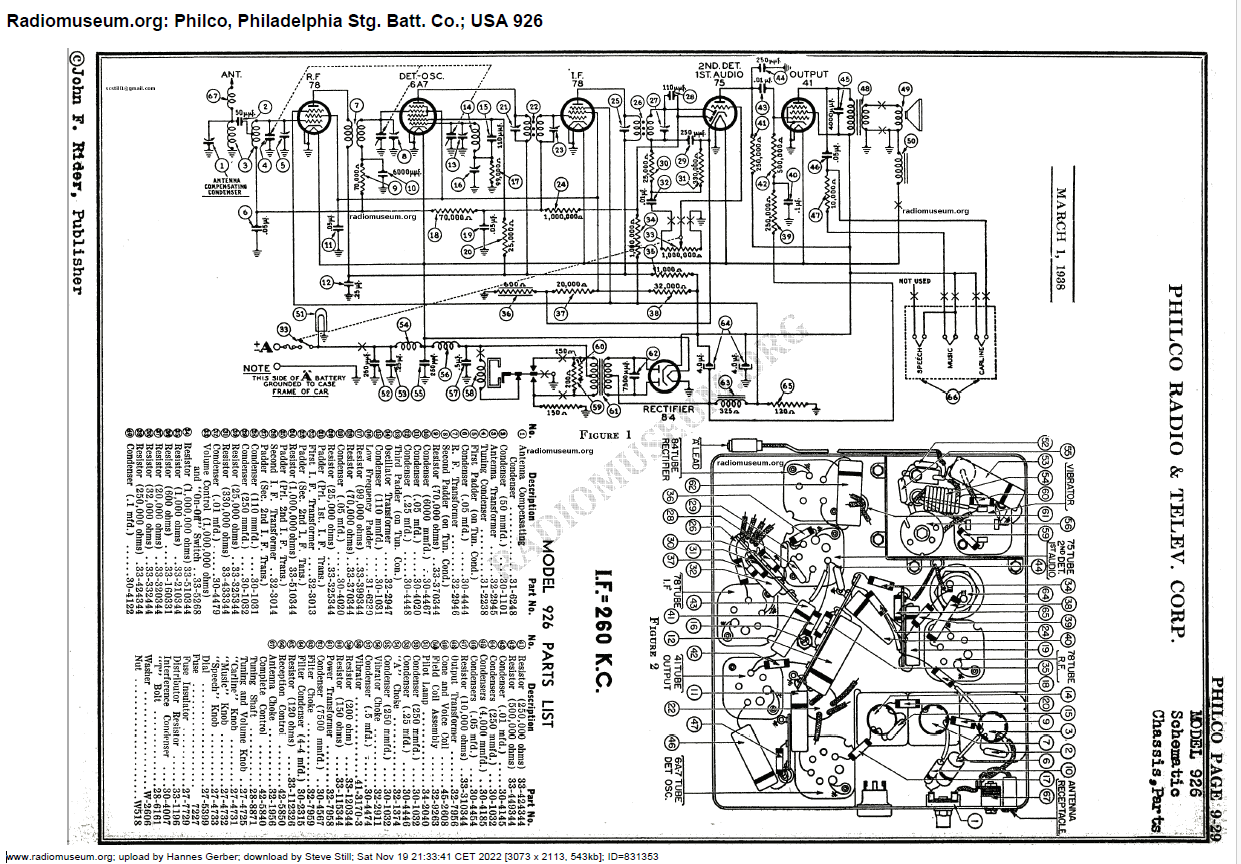
The Philco 926 radio was a car radio from the 1930’s that was powered from the car's 6v battery. The radio was a 6 tube design that had a 84 rectifier, 78 RF amplifier, a 6A7 mixer oscillator, 78 IF amplifier, a 75 dual diode triode 2nd detector, and 41 output pentode. The original speaker was driven by a field coil
The model of the radio we are searching for is the Transitone 51,000. We found an article dated August 1930 that lists the following cars "Wired to Transitone specifications: Chrysler, Desoto, Dodge, Franklin, Hupmobile, Jordan, Packard, Peerless, Pierce Arrow, Studebaker". https://forums.aaca.org/topic/188-1920s-car-radio/
https://philcoradio.com/library/index.php/philco-history/philco-auto-radios/
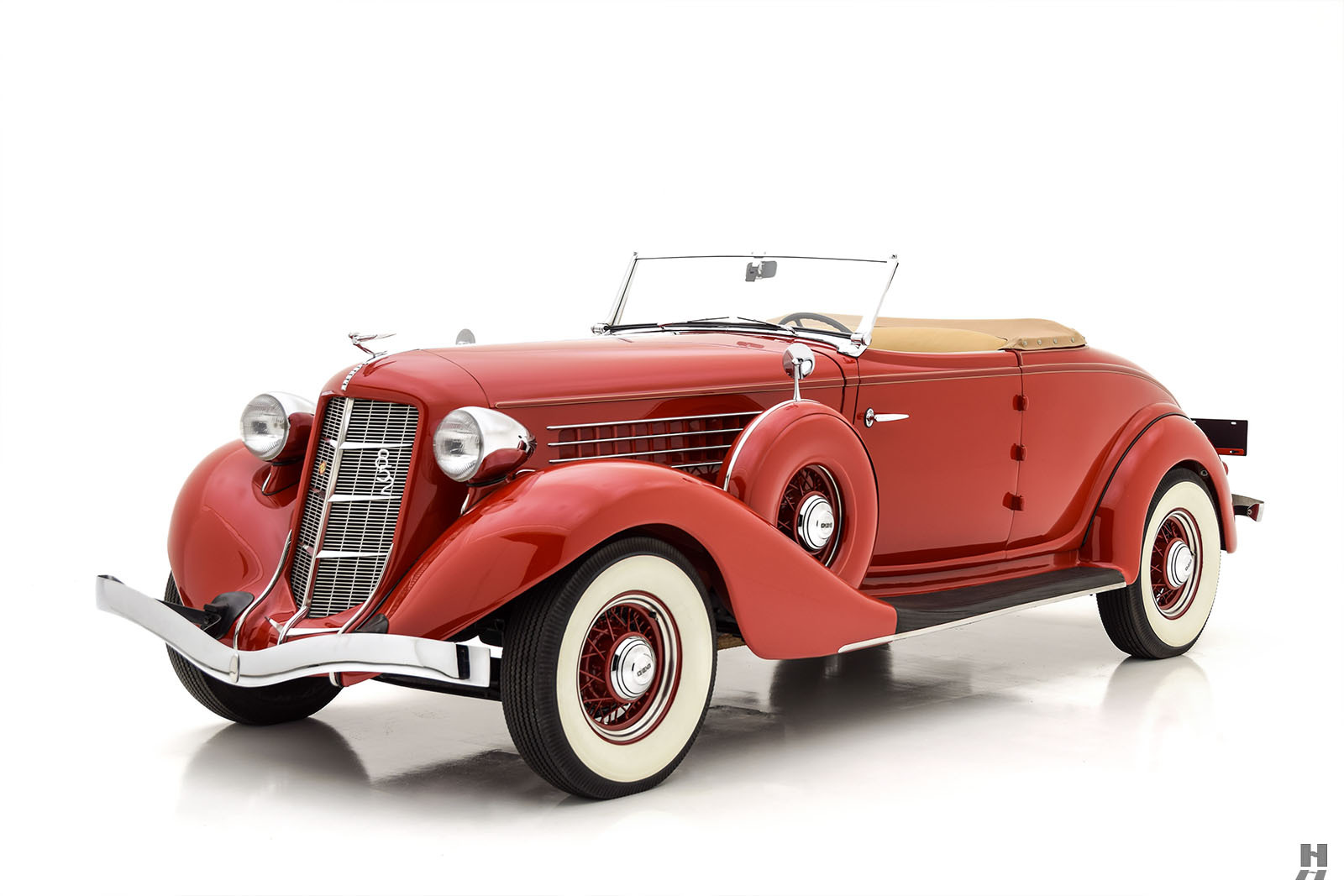
1936 Plymouth Coupe
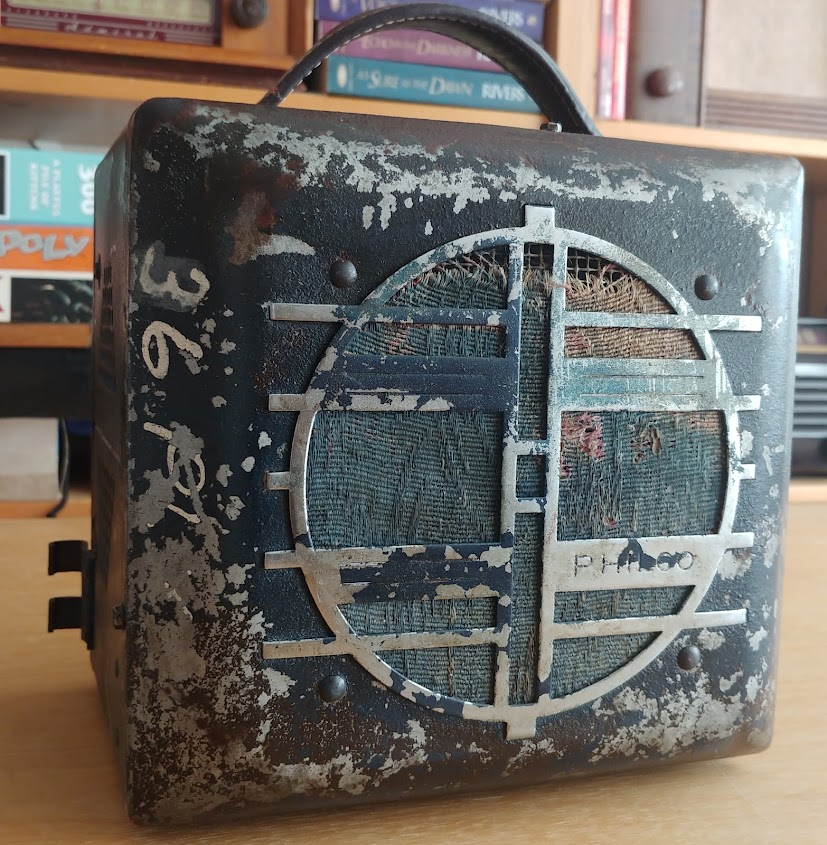
The car that this radio may have resided in is the 1936 Plymouth Coupe. What a beautiful car. Think I wil keep my eyes open for one. As the timeframe of the Philco 926 radio is correct and the markings of “36 Ply” on the cabinet.
Cabinet / Chassis Layout
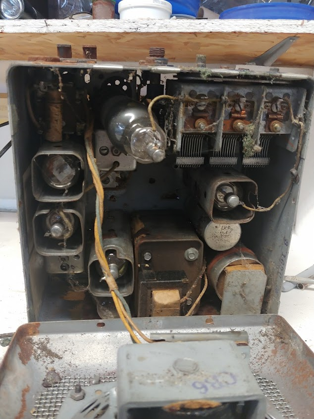
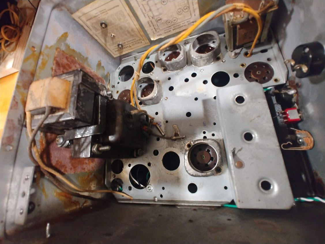
The original radio chassis layout is very dingy, filled with many old worn out parts. These will be removed and possibly used in another project if still good.
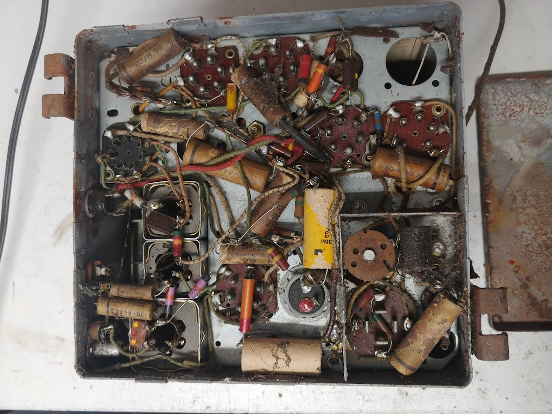
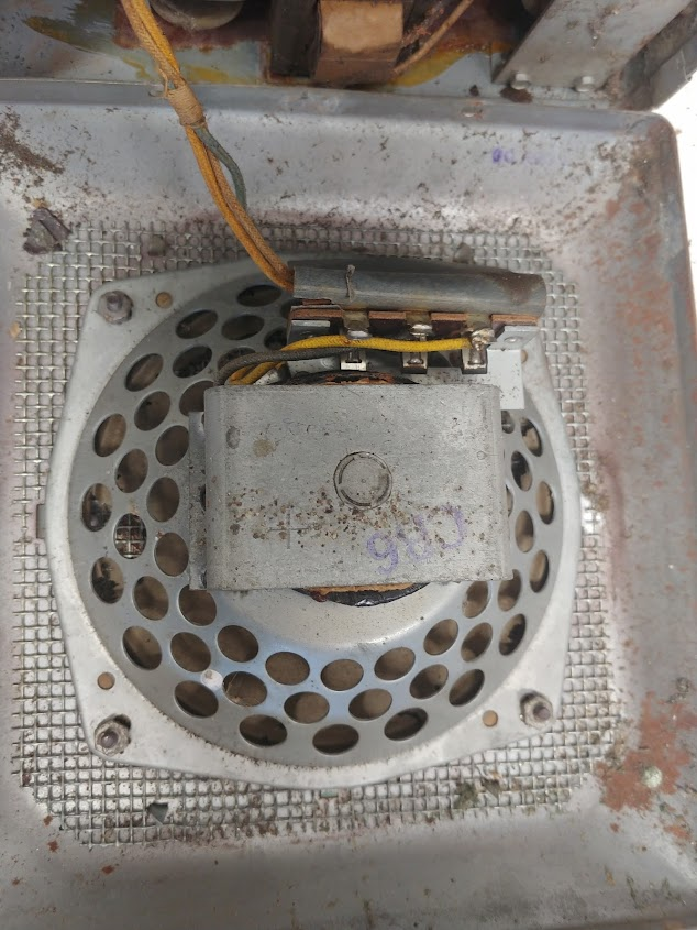
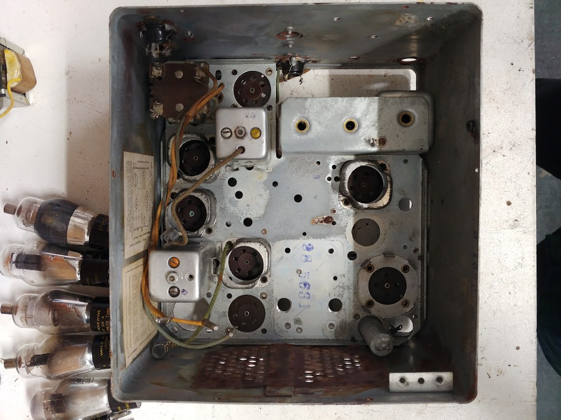
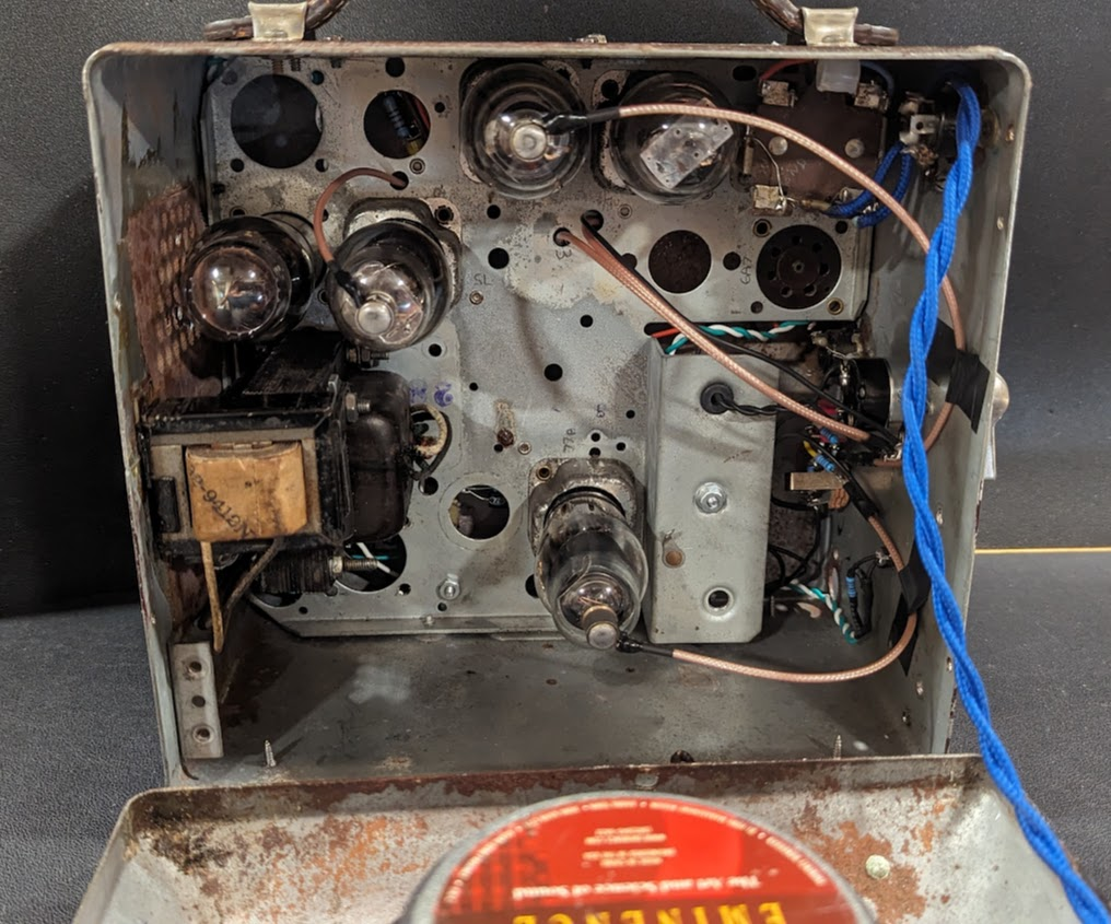
The tube side of the original chassis was filled with tuners, power transformer, IF coils, vibrator, filter cap can and other parts that will be removed and used for future projects. Several of the tubes and the output transformer and choke will stay a part of this project. Similarly the speaker was worn beyond use and had some insect eating the paper cone so it will replaced with a decent 6” guitar speaker (the largest that will fit).
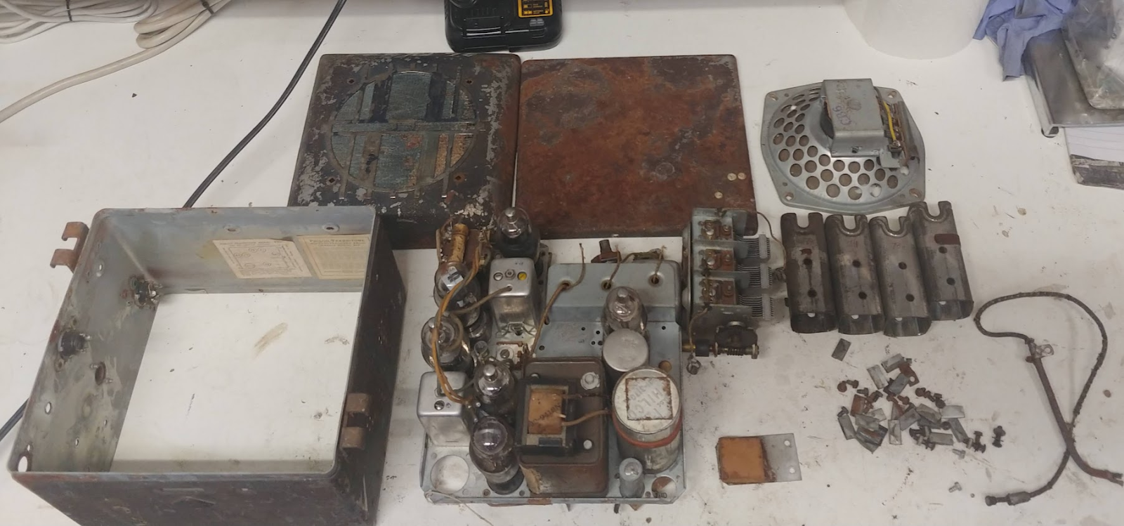
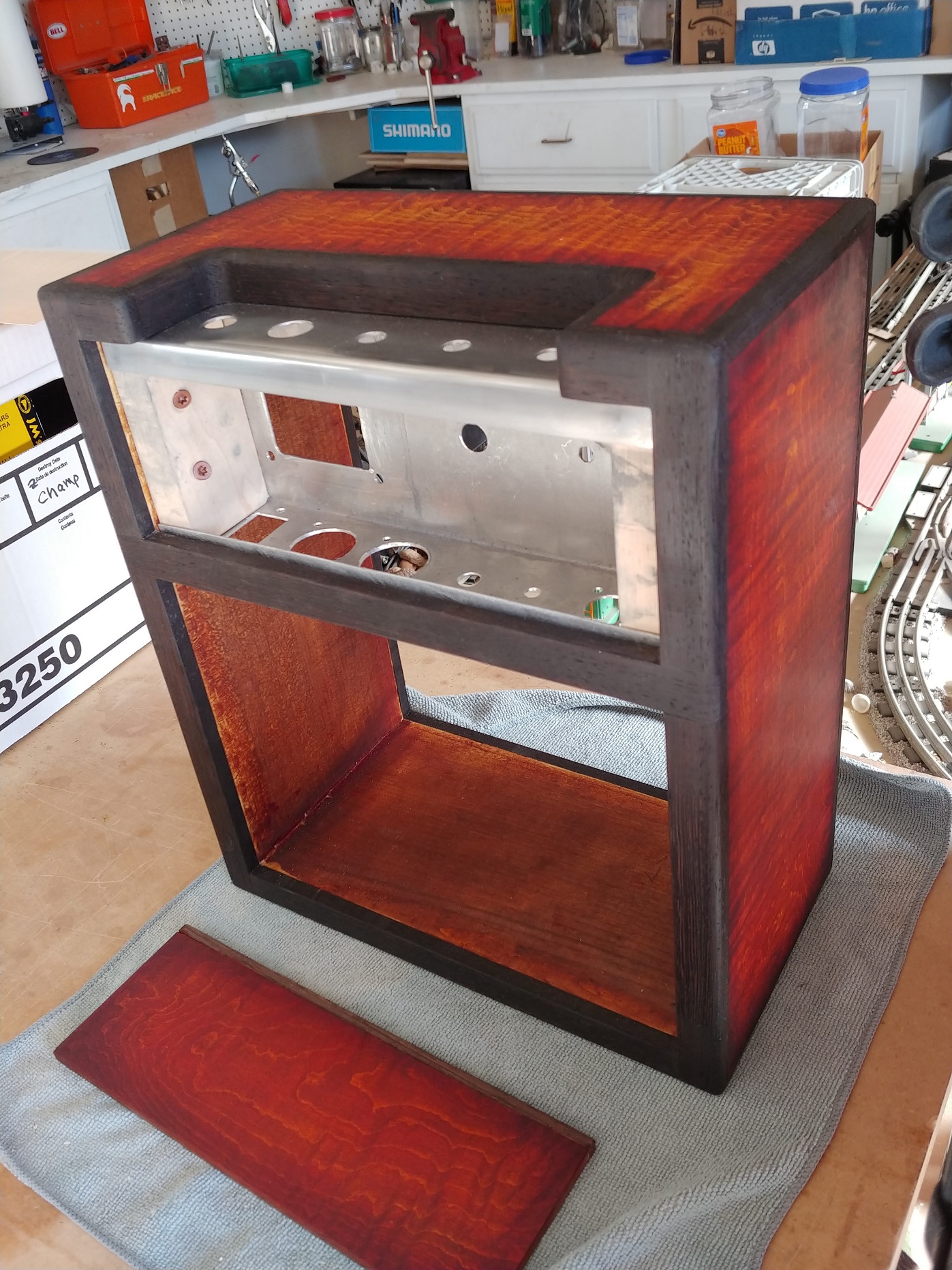
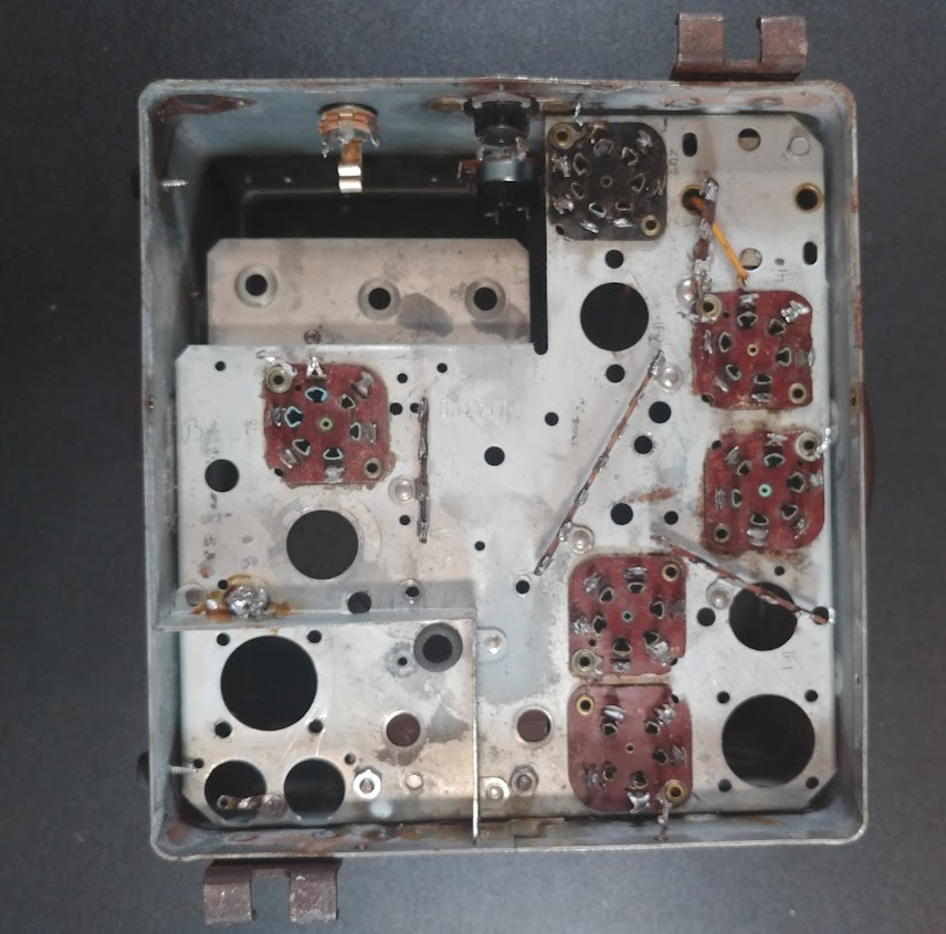
After stripped down its pretty clean
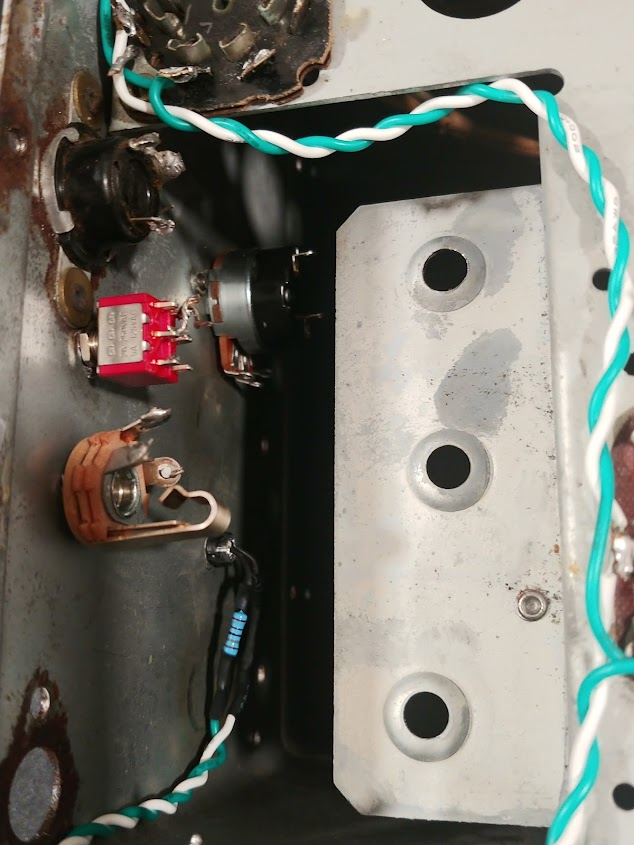
Power transformer and choke mounted and looking very much like they belong as original. As well the combo volume pot/switch, input jack, LED pilot and channel selector switch installed on the opposite wall. Existing Output transformer remains in the upper right corner.
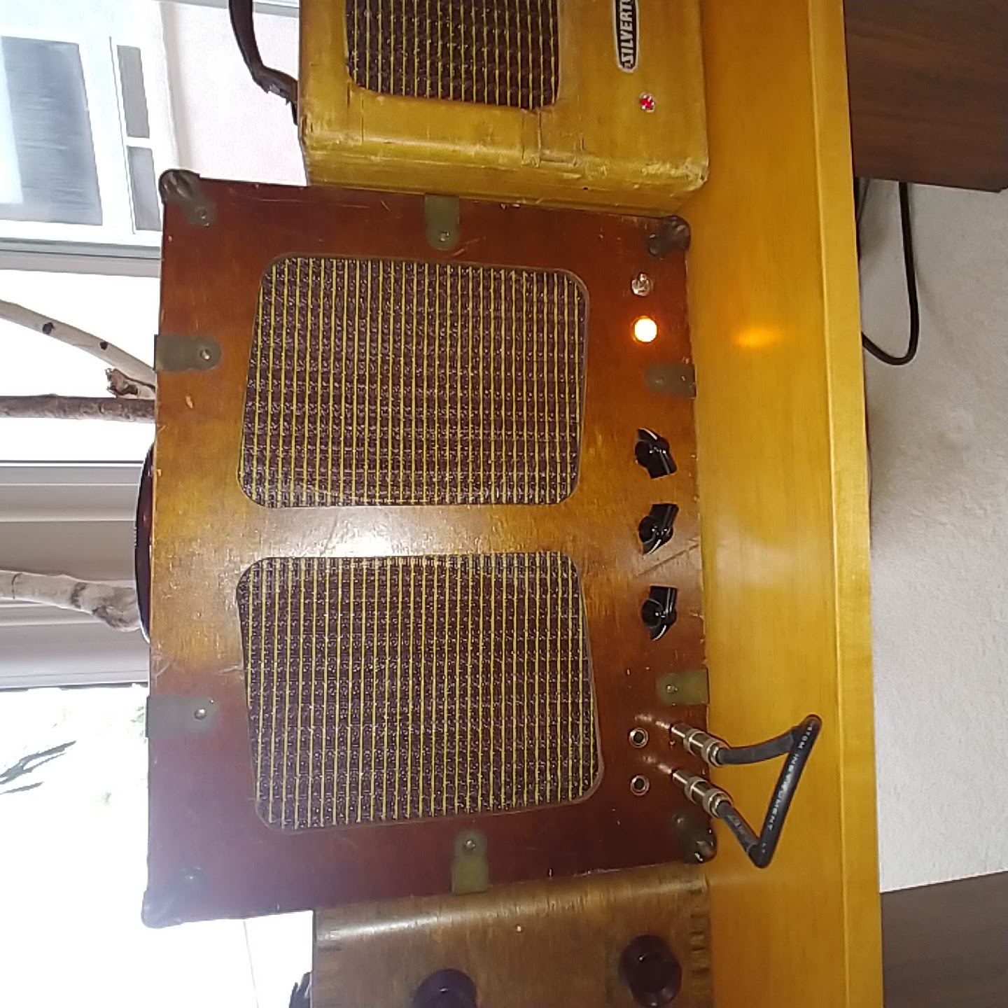
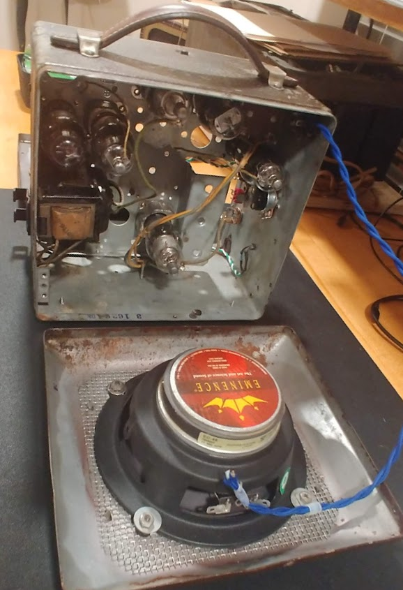
A ”ibg” 6 inch Eminence Guitar speaker is custom mounted to the front panel. The panel lays flat for service on the Phirty6 tube side. Great booking blue speaker wire too. Nice leather handle mounted to the top of the cabinet
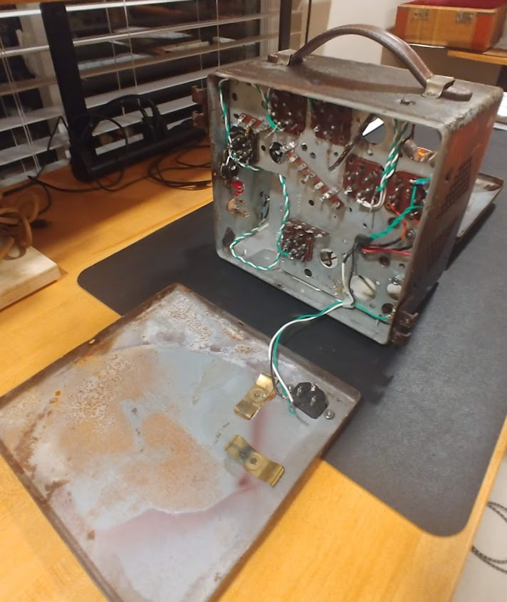
Heater wires installed in white/green twisted pair to ensure proper pin connection. Back panel with AC power plug designed to lay flat for component side service.
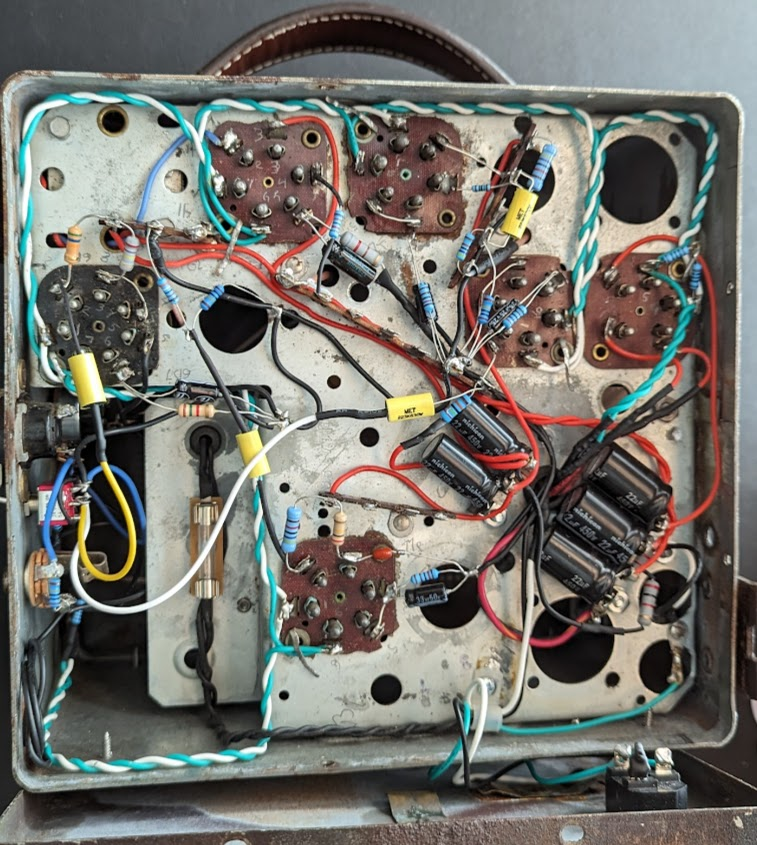
All components for the Triode channel are mounted. Power supply filter caps and dropping resistors shown in the lower right corner, All HVDC (red wires) are located away from the 6v AC heater wires (green/white) for noise reduction. It was decided to mount the 2A fuse inside the cabinet, easy to remove the back panel if required to replace.
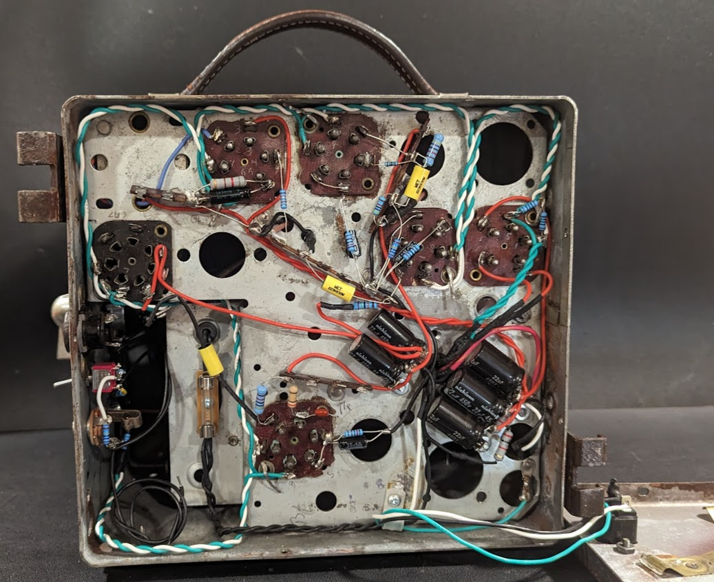
The signal wires are interfaced using coax (one side ground for noise reduction) connected to the control control grid cap on top of the tube or from the volume pot. As an added bonus because the signal lines are on the other side from the AC and HVDC there is even less noise induced. This is a very quiet amp.
Below the pentode channel components are mounted.
Circuit Design
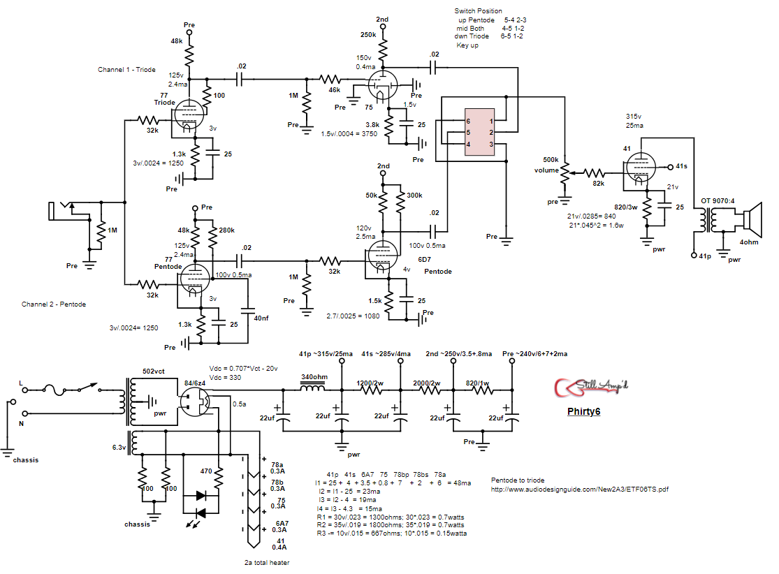
The design of the circuit is mostly based on the tubes and layout that came with the Philco 926 radio. With 6 tube sockets it allowed for two channels; one channel with a triode preamp and triode second stage and one channel with a pentode preamp and pentode second stage. The channels are switchable at the input: triode channel only, pentode channel only, or triode and pentode together, The common output stage made use of the #41 tube in class A single ended design. The original Output Transformer was used into a 4 ohm eminence guitar speaker.
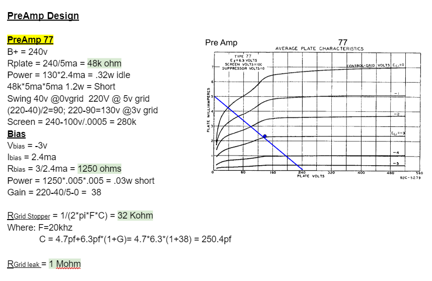
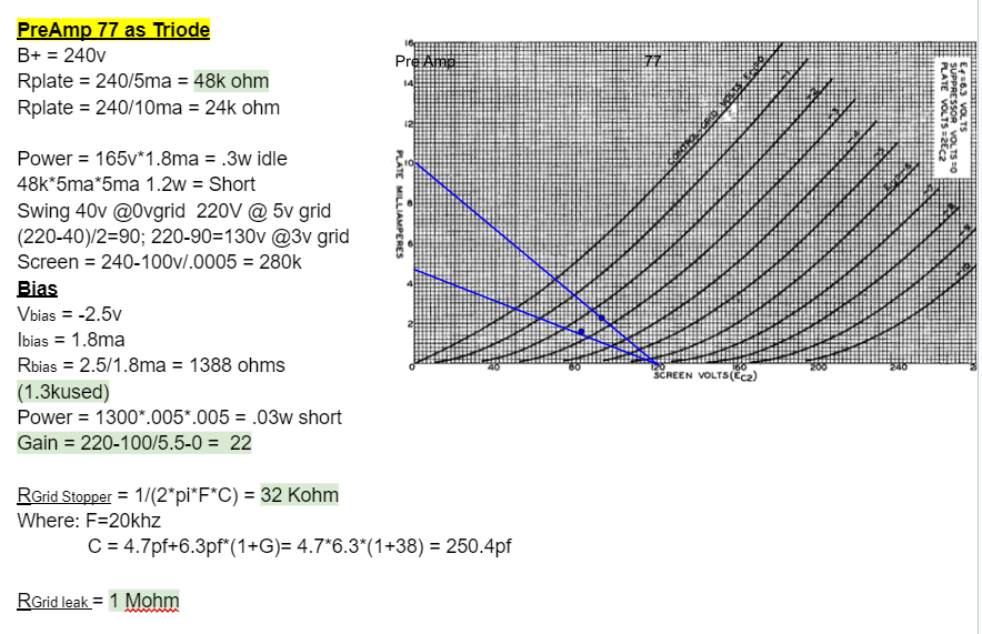
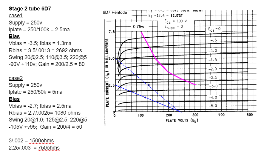
The radio included two #78 pentode tubes that would be used for preamp, except that these are remote cutoff. So it was decided to swap these for it’s evil twin #77 pentode that are sharp cutoff, more suitable for guitar amp. In the Triode (T) channel the 77 will be operated as a triode (shown as wired in the schematic); while in the Pentode (P) channel the 77 will be operated as pentode. In both channels the 77 is designed to provide a balanced operation with the idle point in the center of the load line.
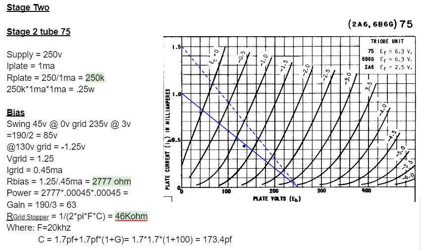
The design for the second stage with the #75 triode tube is shown in the load line calculations below. Again balanced operation (idle operation in the center of the load line) was desired for the most clean headroom.
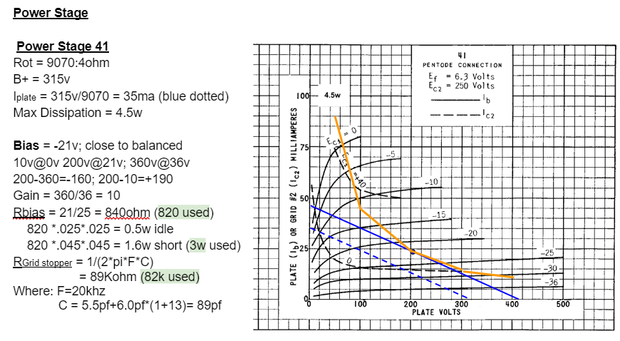
The #41 power pentode output tube is designed for balanced operation at a max dissipation of 4.5w. Shown in the load line calculations and schematic below.
References
1 Discussion on mixing triode and pentode channels https://el34world.com/Forum/index.php?topic=31051.msg342161#msg342161
2 Discussion on early socket heaters https://el34world.com/Forum/index.php?topic=29688.msg326827#msg326827
3 Discussion on Patina https://el34world.com/Forum/index.php?topic=29643.msg326566#msg326566