Overview
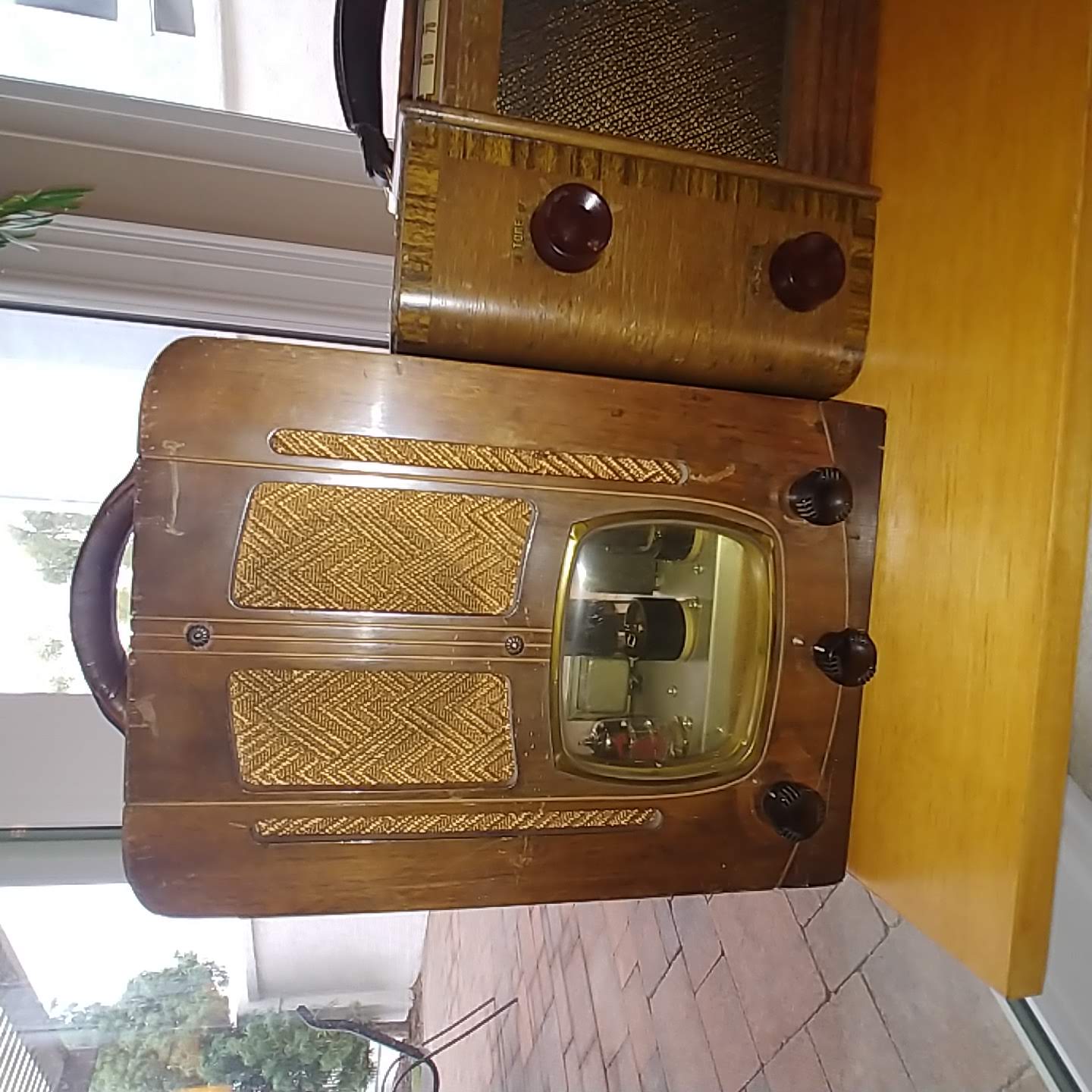
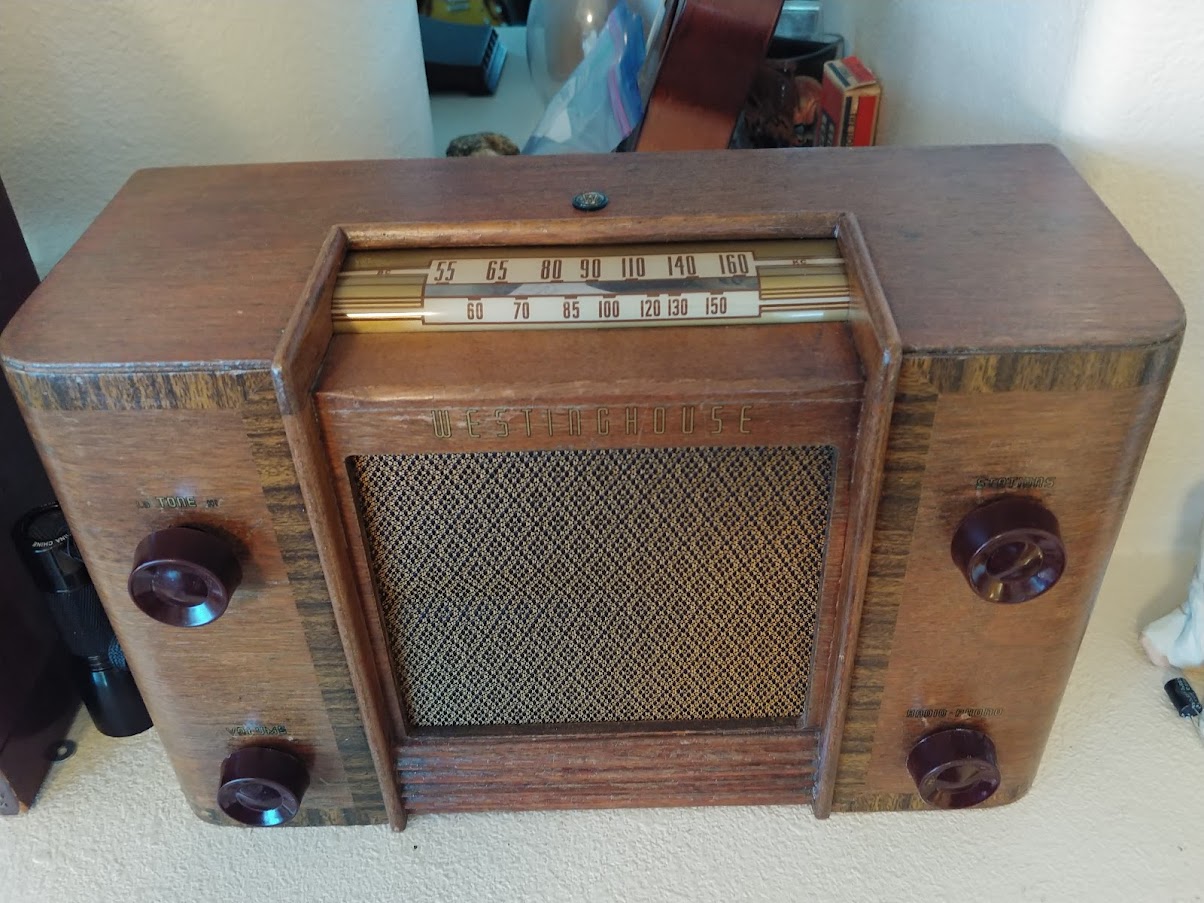
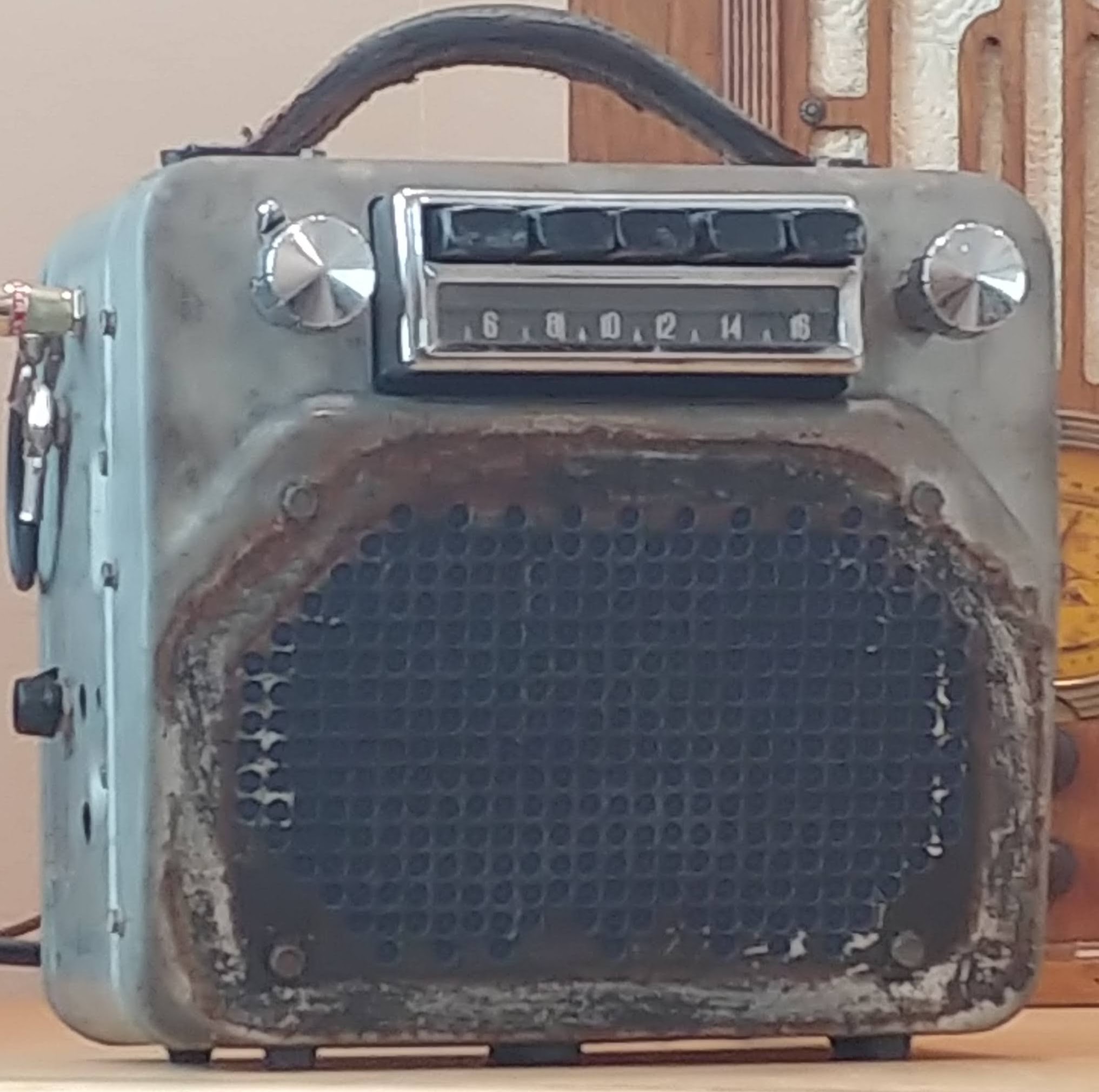
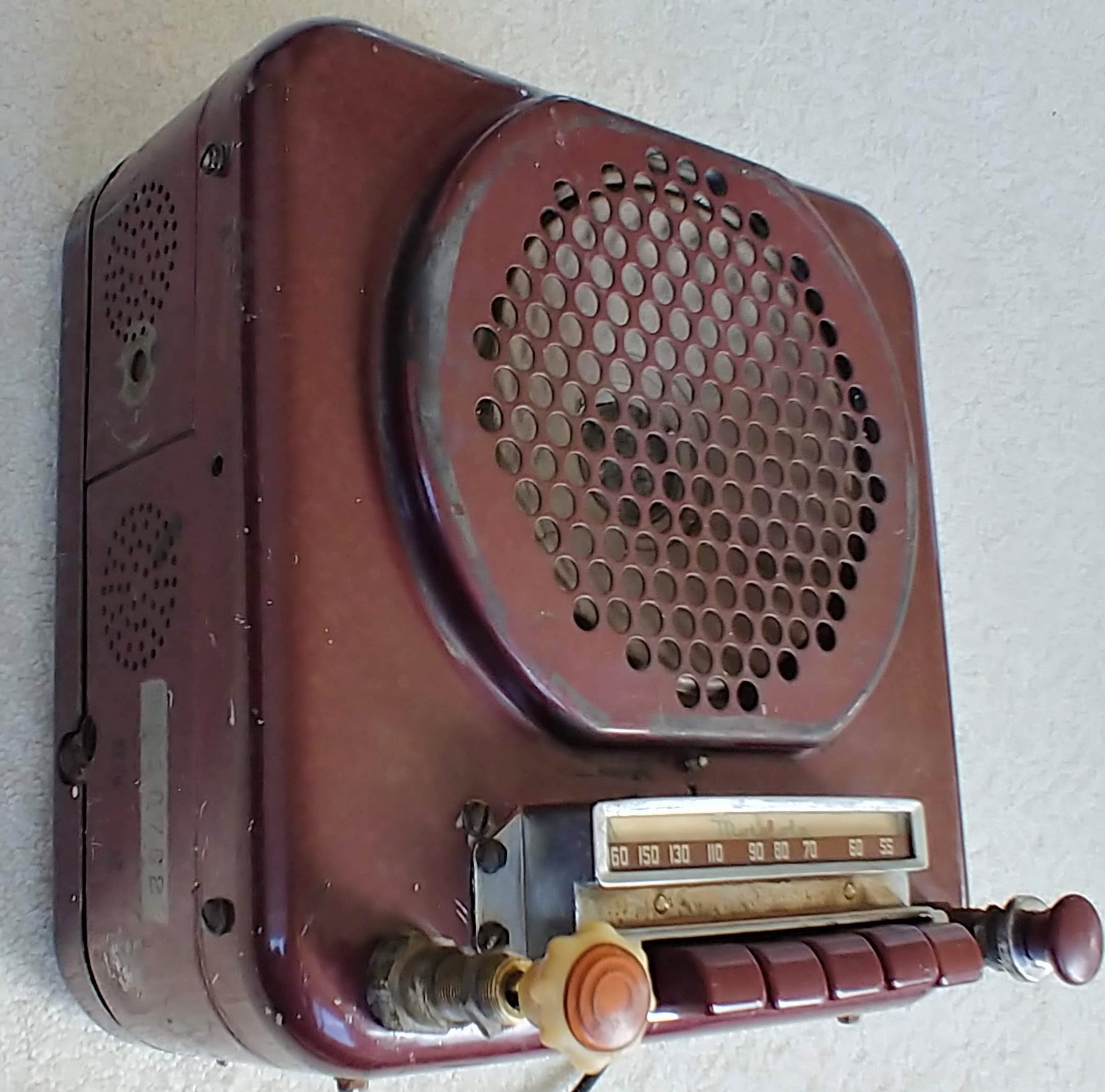
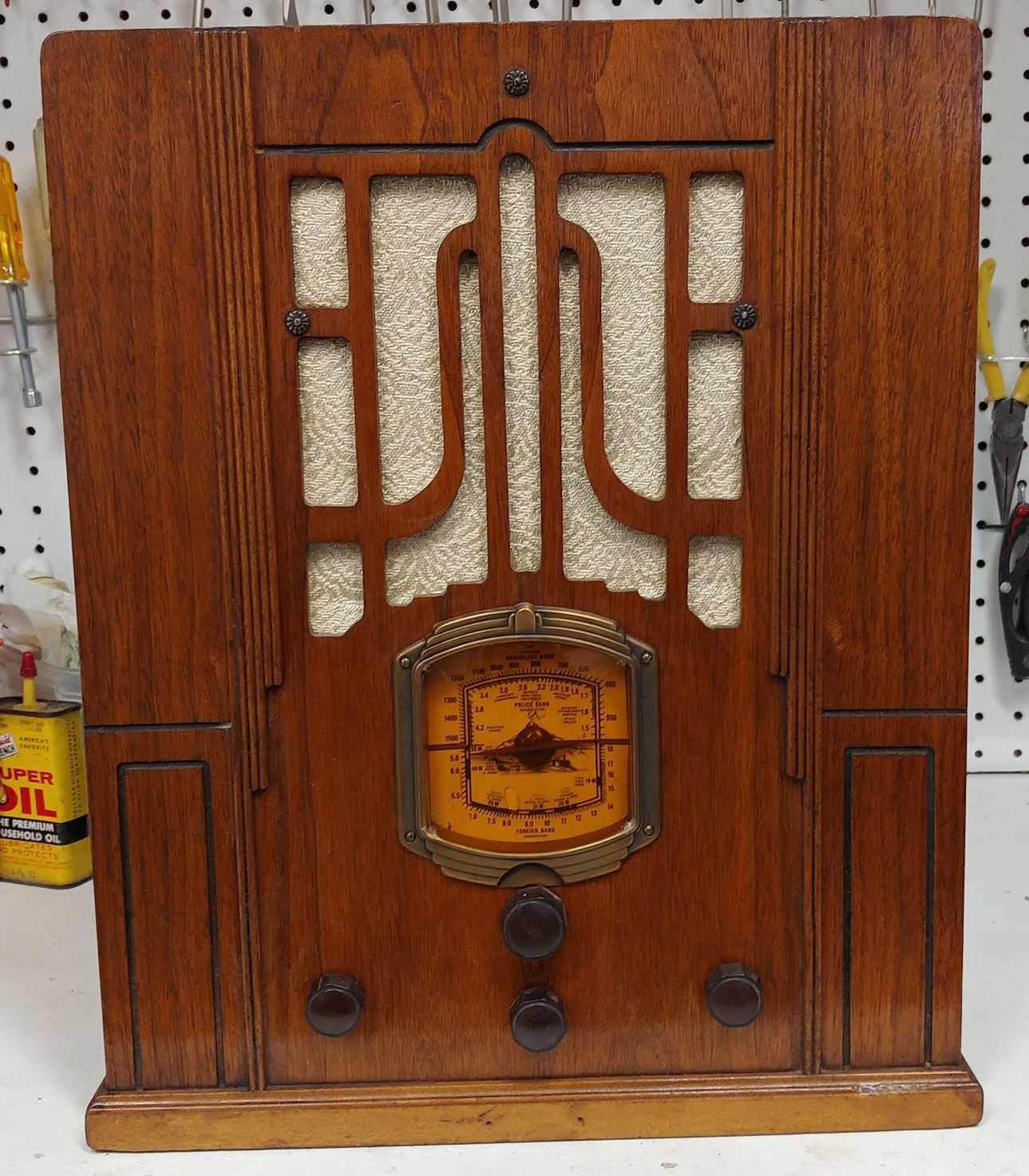
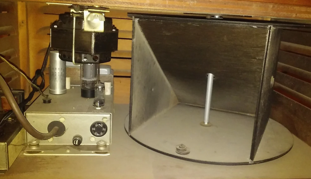
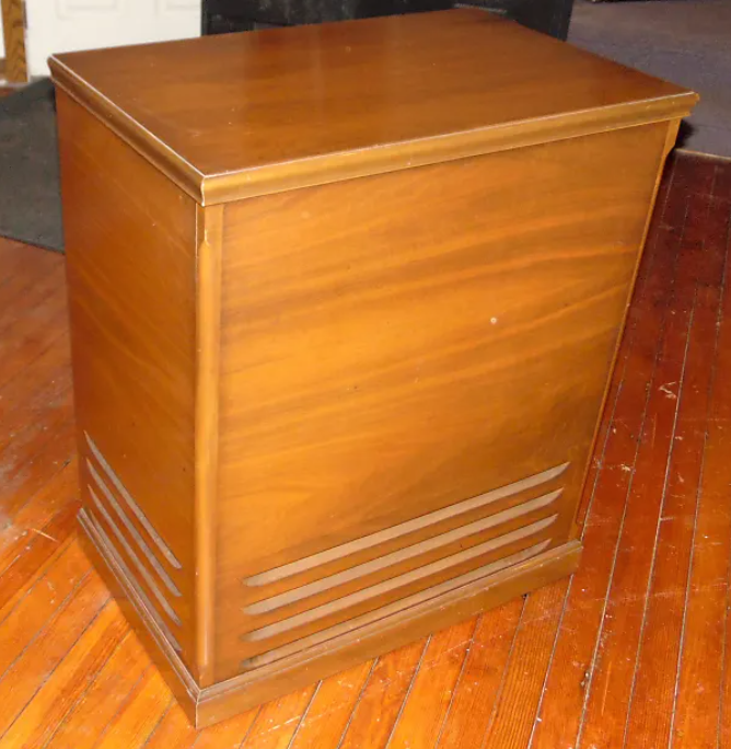
The Leslie 25 Booster Amp was the power amp in the Leslie rotating speaker in the Leslie 25 Orpheus rotating speaker cabinet. The design was likely from the late 50’s to early 60’s. A few pictures below to show the cabinet style and the location of the booster amp within the cabinet. The amp was perfect for adding a preamp tube and converting into a guitar amp. That build is the subject of this essay.

The original Leslie 25 Speaker Cabinet and location of the booster amp inside the cabinet
Original Amp
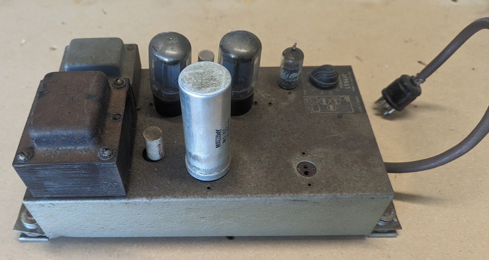
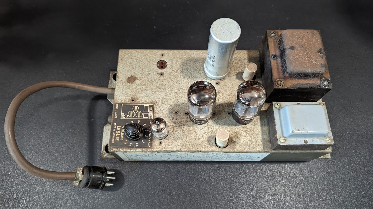
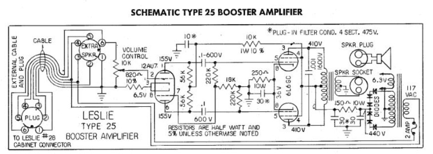
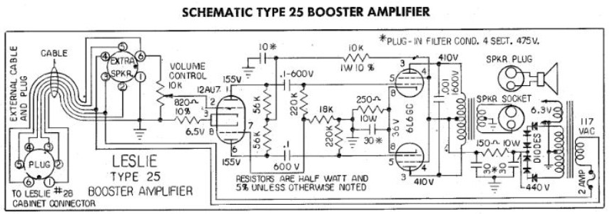
The original amp was described as a 25w booster amp. Likely referring to the fact that it was a power amp only that drove the Leslie Organ speakers. The amp is a push pull design using two 6L6GC power tubes driven by a 12AU7 paraphase phase inverter. There is a volume pot that precedes the PI. AC power and speaker out are received by a 8 pin octal cable, that connects to the preceding stage likely including a preamp, but not available here.
Lots of space inside the cabinet to add the guitar preamp. As well the filter caps in the can were out of spec and likely dried and in need of replacement.
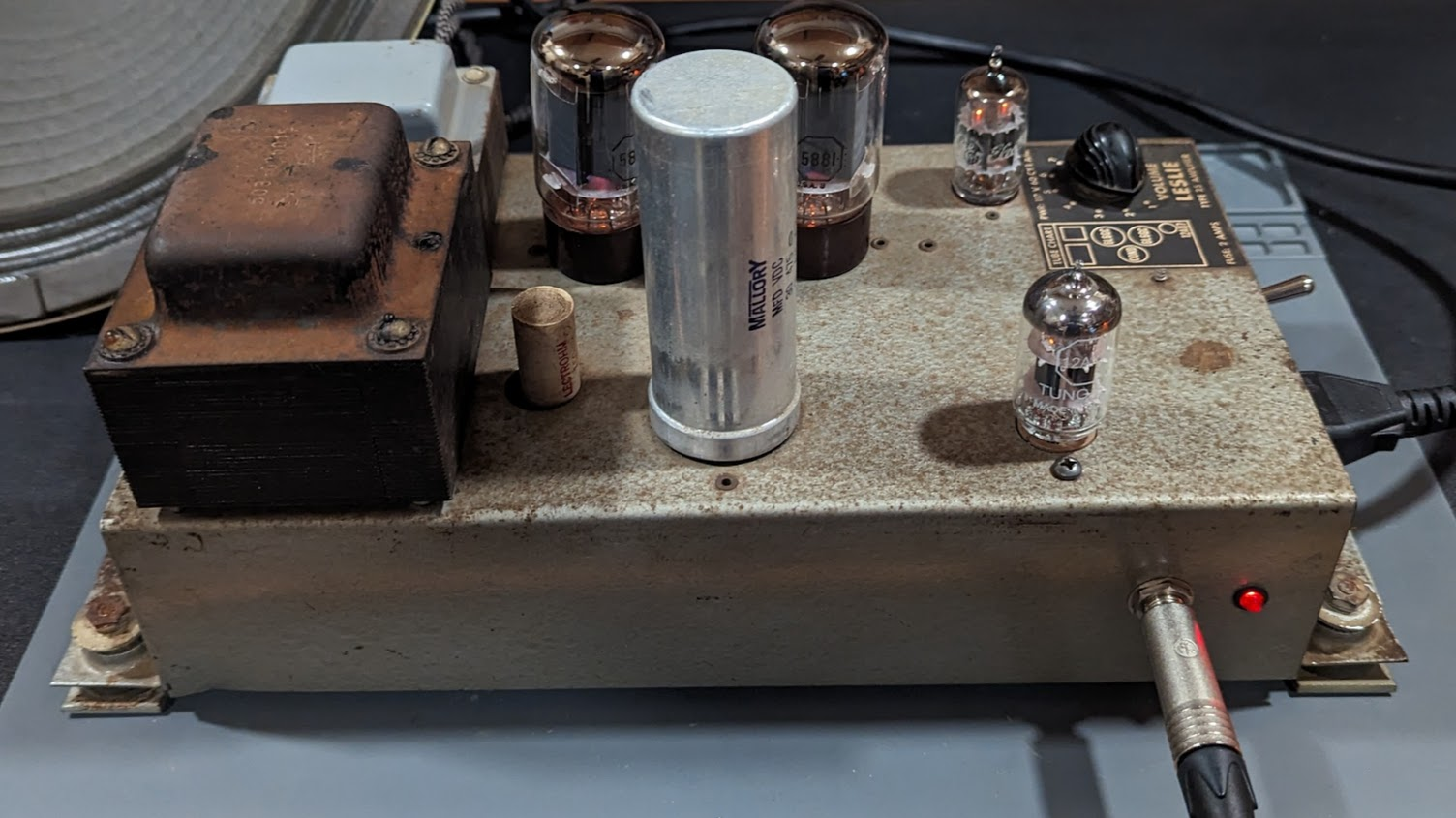
Chassis Cleaning and Modification
Cleaned up as good as possible without repainting
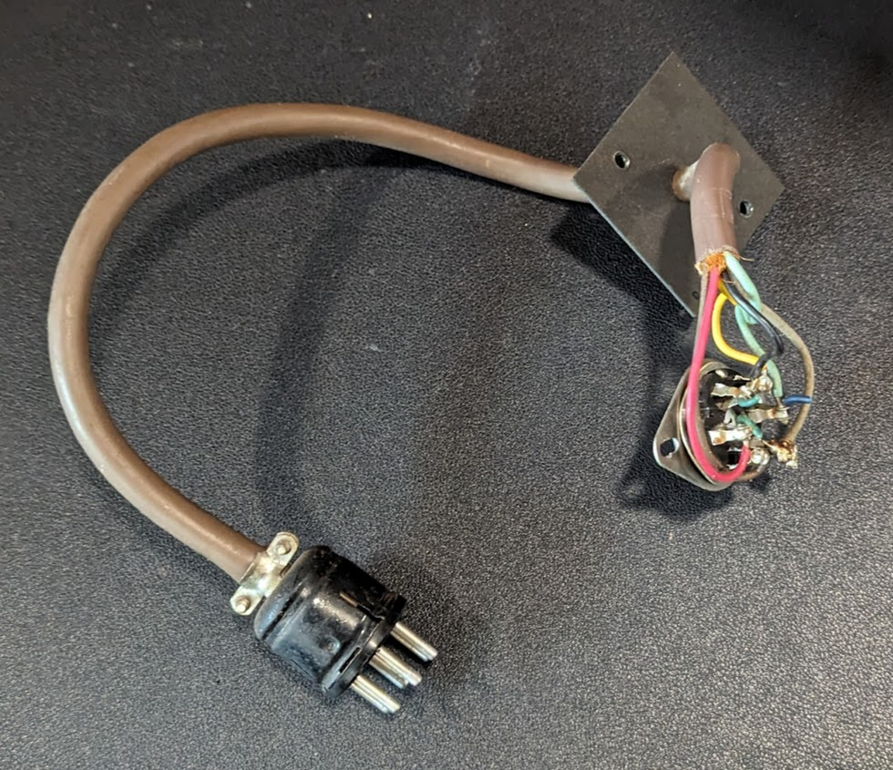
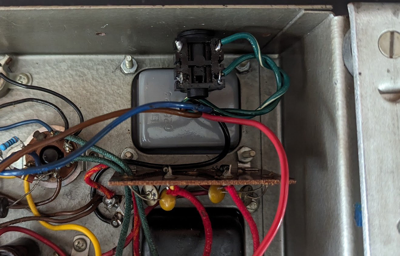
The side cable and socket were removed and the holes patched with steel plate to make room for the new on/off switch and AC power socket.

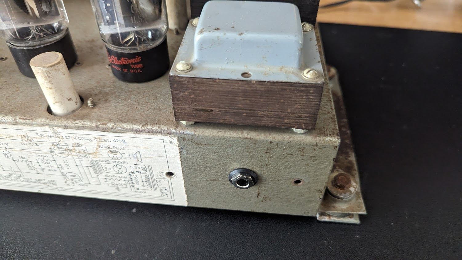
The original extra speaker jack was replaced with a 9 pin tube socket for the preamp tube. As well a guitar input jack and LED pilot light are added.

The new speaker jack is located on the back panel close to the output transformer
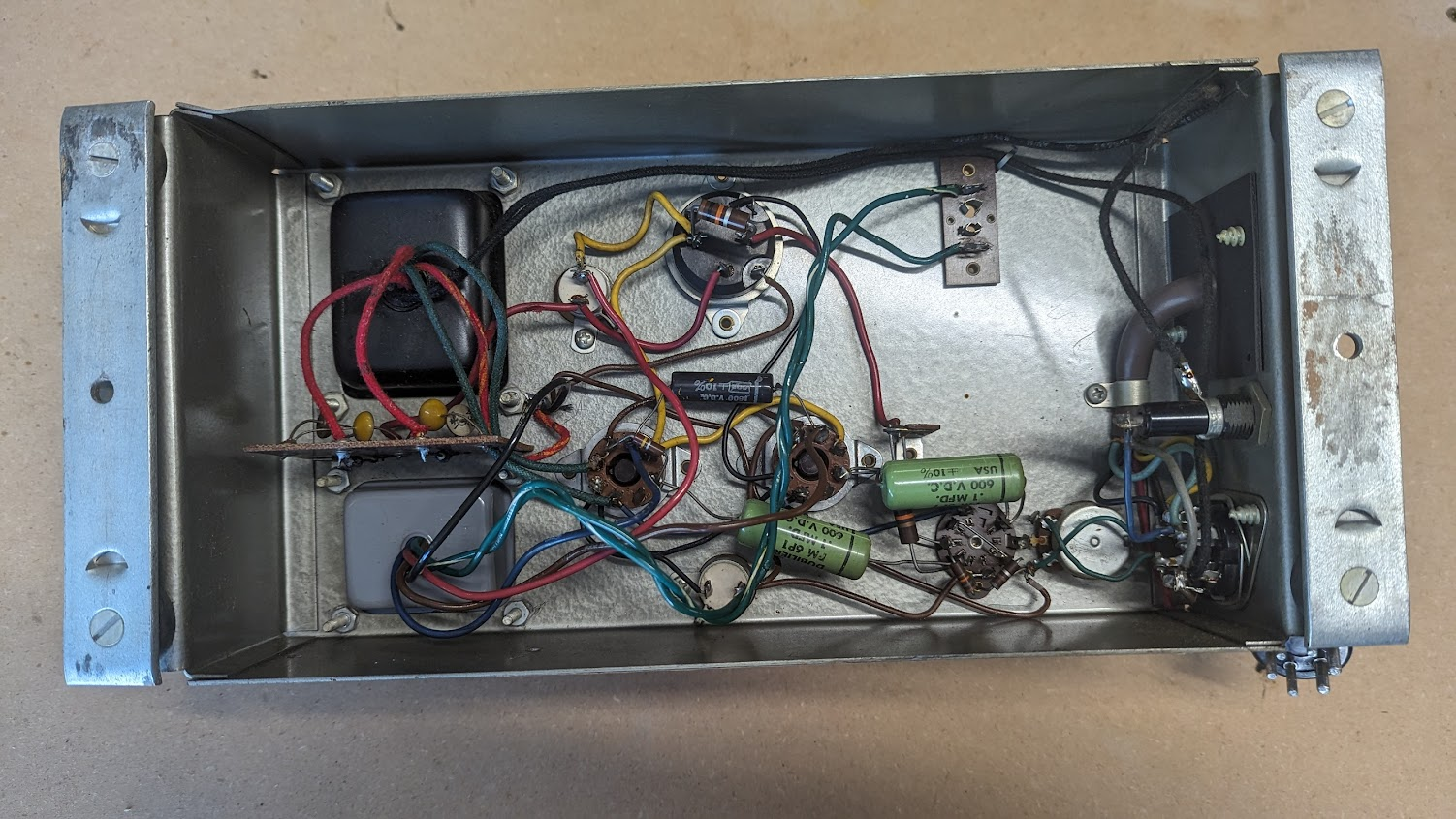
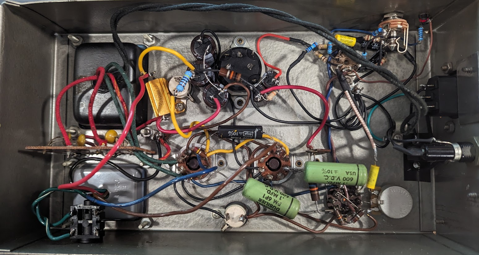
Adding New Filter Caps
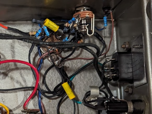
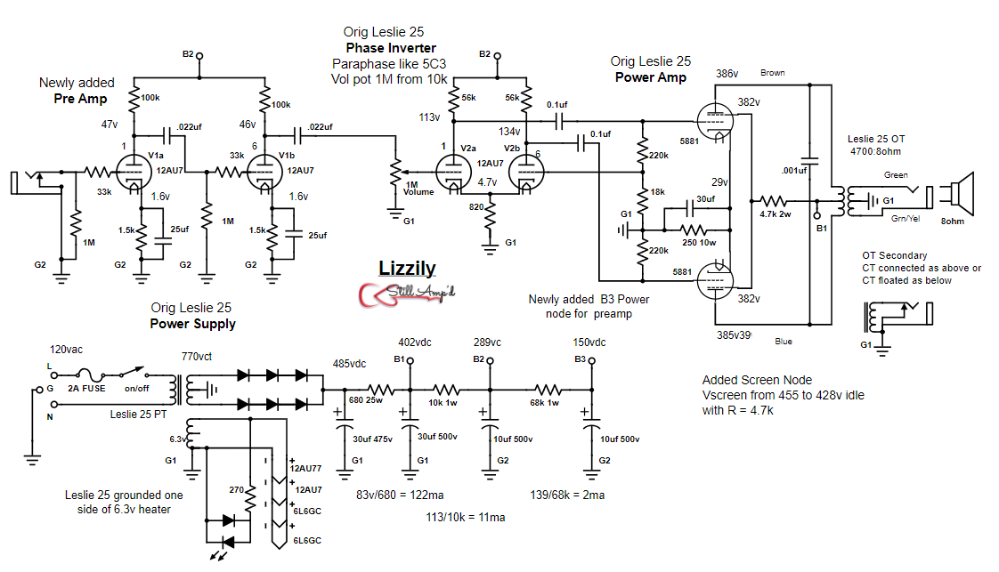
The original Mallory filter can caps had fallen out of spec and were likely noisy. So these are replaced with modern caps inside the chassis. Plenty of room around the original filter can, An additional power node was added to power the preamp tube. The original filter can is left in place on the top chassis for good aesthetics. The new cap on the upper left side (positive terminal black wire) is not a filter cap but used for power tube cathode bypass as in the original design. All new caps are held in place with double sided tape. Although once wired in place they do not need the tape.

PreAmp Stage
The preamp tube is the 12AU7 which is a dual triode. This allows two input gain stages. Originally the plan was to use a 12AX7, but the dual stage gain was just too much so the 12AU7 was used instead. The design is shown in the schematic, using 100k plate resistors and 1500 cathode bias resistors with 25uf bypass caps.
Speaker Output
The output transformer had a strange grounded center tap on the secondary. The impedance measured at 4700:8 ohm across the coil with the grounded center tap. Since this is a good load for the 6L6GC pair, it was decided to isolate the speaker jack from the cabinet allowing the secondary center tap to provide the ground.
The final circuit design and layout includes some updates from the original Leslie schematic to improve tone and operation. First the screens of the power tubes were actually slightly higher voltage than the plates due to the resistive loss of the OT primary, so a dropping resistor was added off the screen power node. There were not any grid stopper resistors on the power tubes; it was decided to add 3k resistors to help tame some of the high frequencies. But these were left out of the final design as the original amp did not have these and the frequency change was imperceptible.
One addition was to increase the first power supply dropping resistor from 10 to 25ohm (25w) in order to reduce the power tube voltage closer to 400v (from 450). This allowed the original GE 5881 Tung Sol tubes that came with the unit to be used. Always “keep it as original as possible” is a good motto.
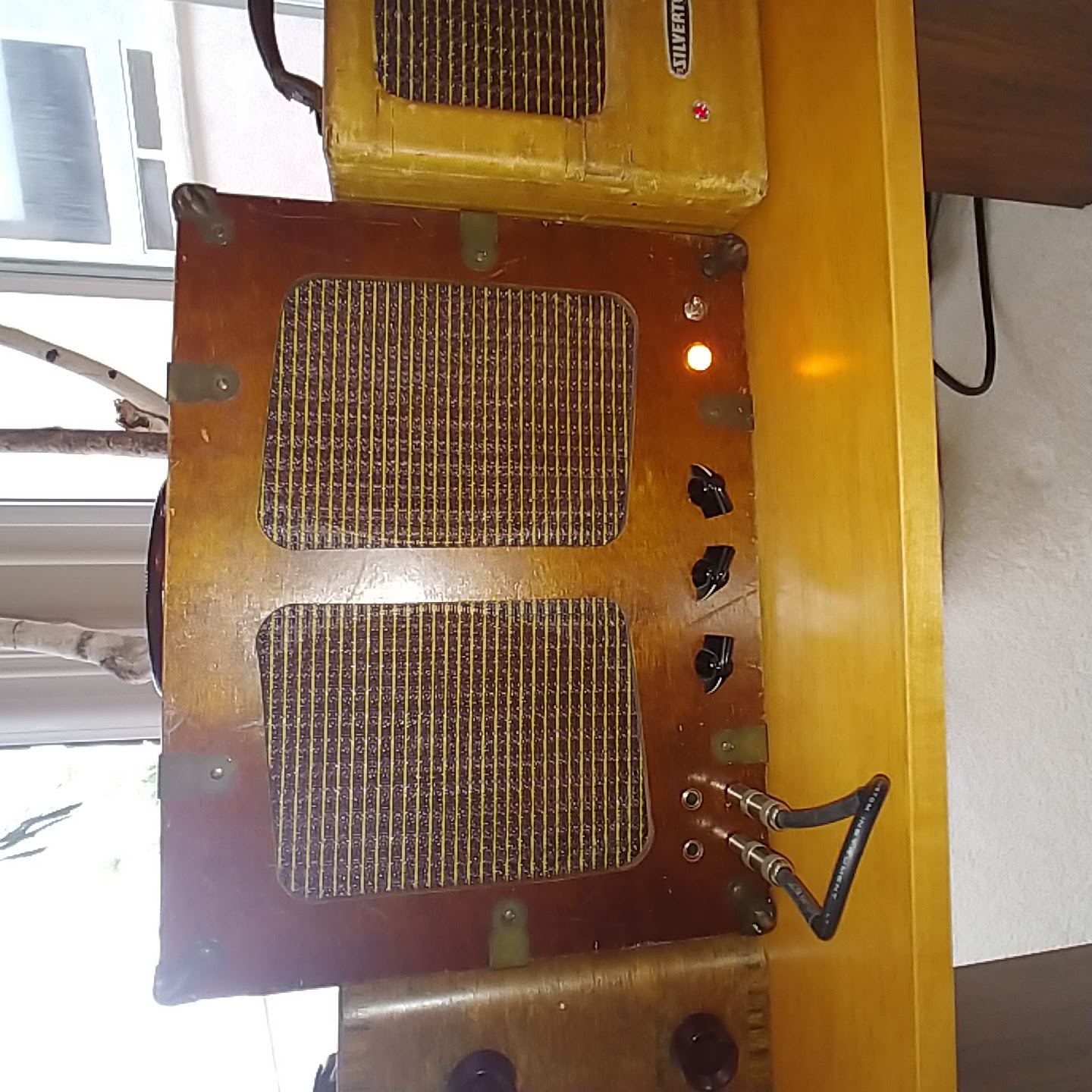
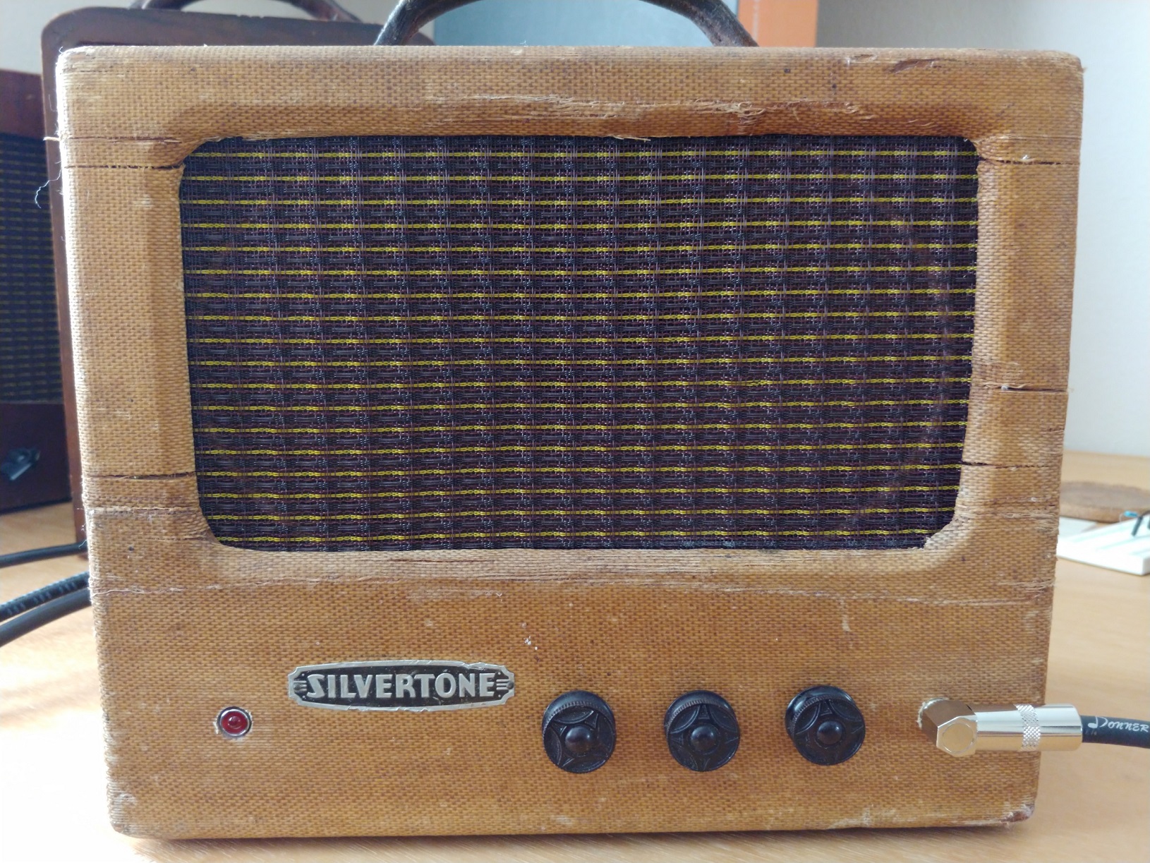
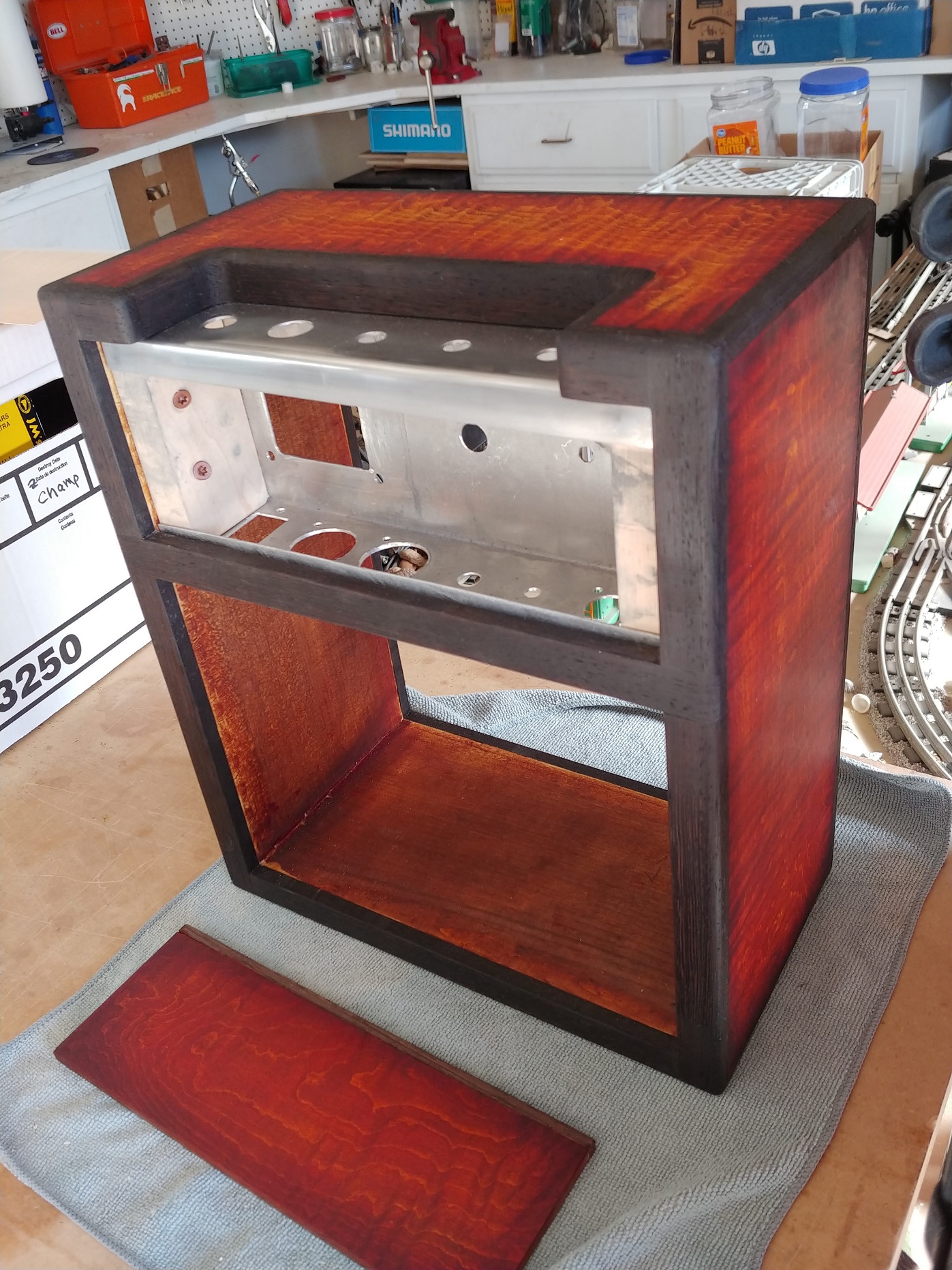
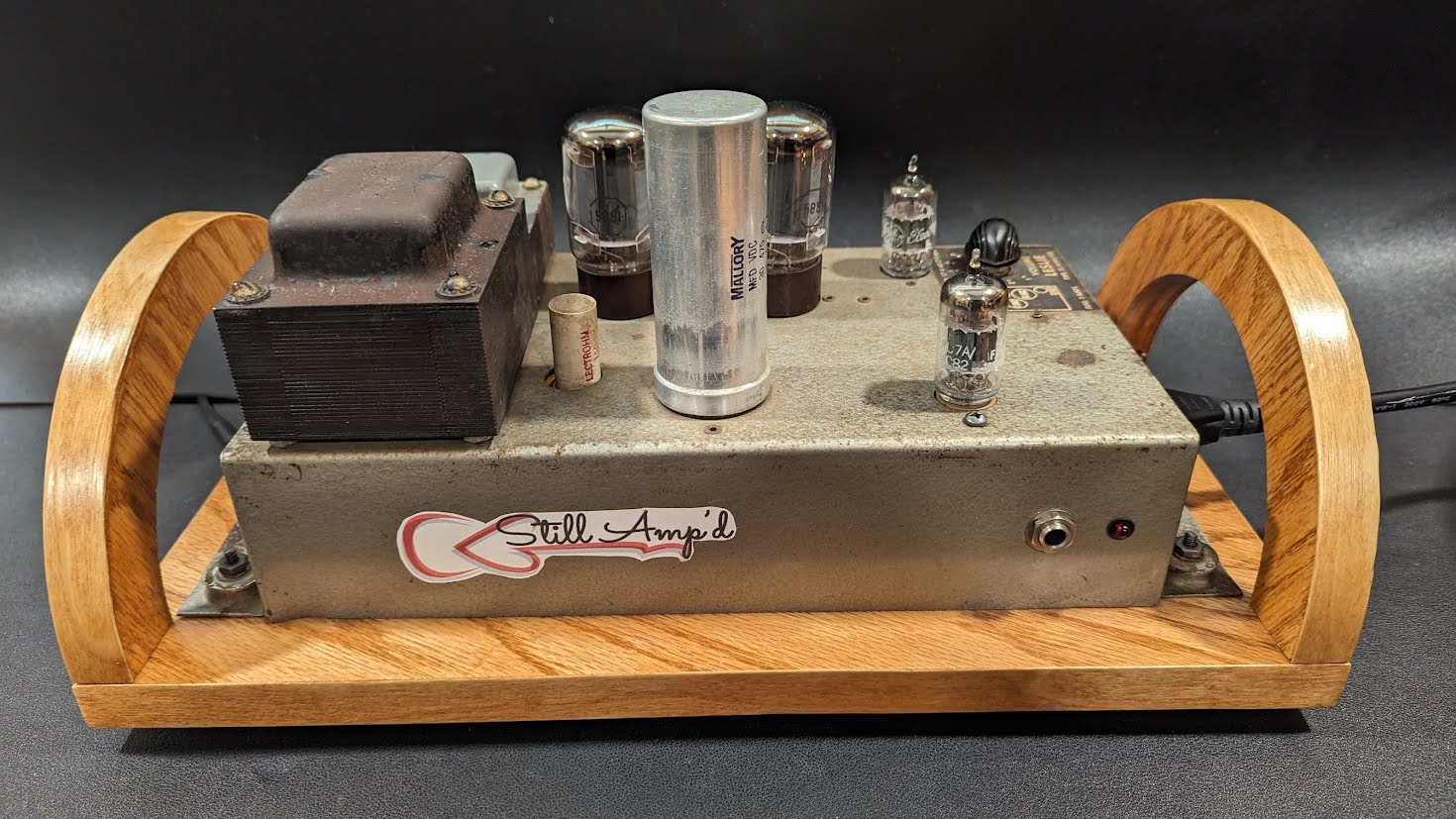
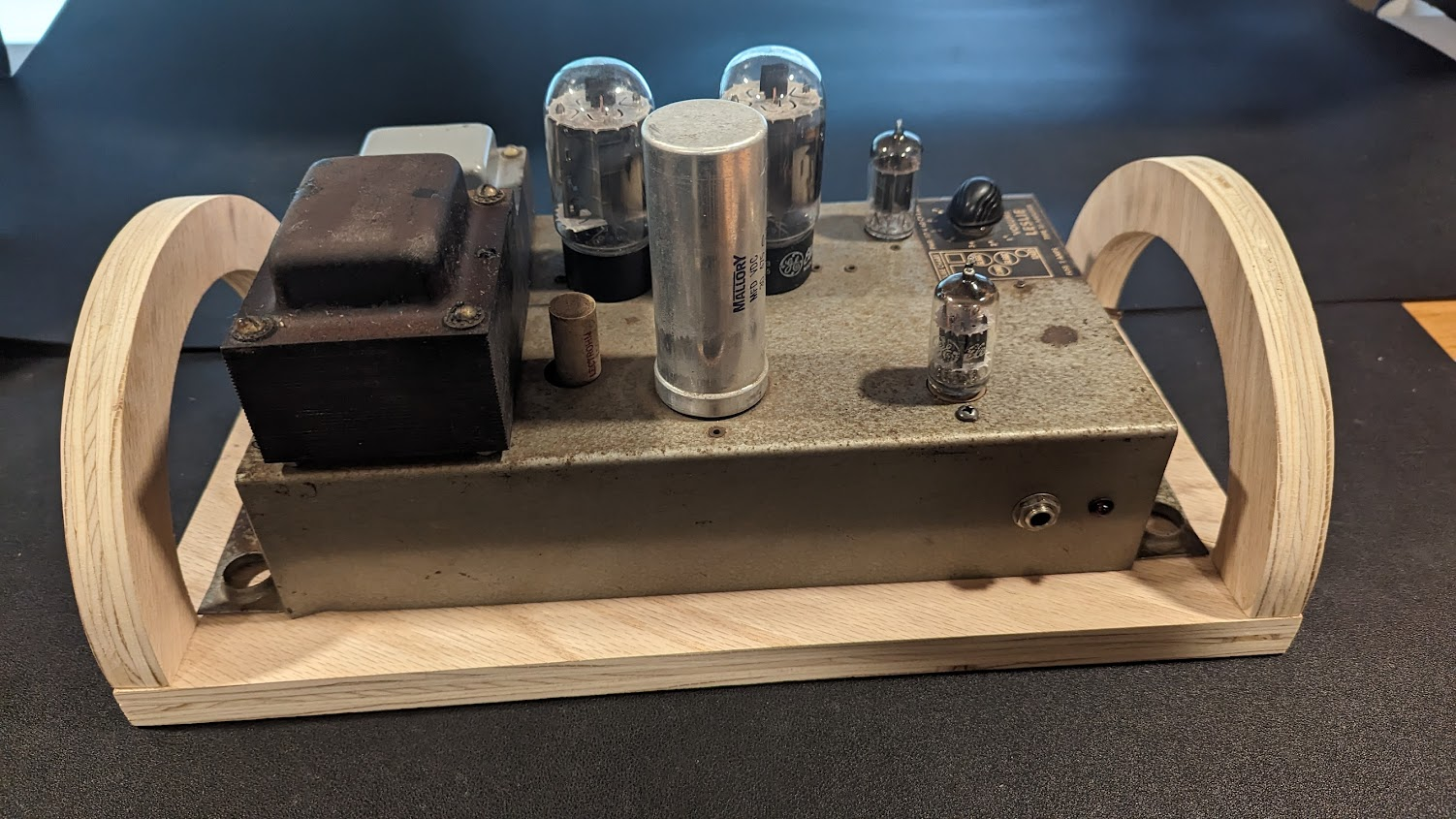
Design Cabinet
The challenge was to figure handles that would not interfere with the side mounted AC cable and switch while having a comfortable and solid handle for movement. It was decided to fabricate an arch type of handle that was high enough to provide a comfortable hand grip. A board was sized to fit the amp and the handles were mounted. The wood was stained and coated with a durable clearcoat.

Some additional mods that are being considered are to add a tone stack off of the volume pot, again to bring some of the high frequencies down. And possibly to float the 6v filament power supply as the current design has one leg grounded. The current hum is very low and so likely not a real issue.
Schematics and Design Calculations
The following are the schematic for the original Leslie 25 booster amp and for the as-built Leslie 25 guitar amp.
Leslie 25 Guitar Amp Schematic
Leslie 25 Design
6.3v current draw
6L6 900ma 5881 900ma
6L6 900ma 5881 900ma
12AU7 300ma
12AX7 300ma
HV power draw total = 170.4ma
ClassAB1 Cathode Biased 410v supply
6L6 plate 100ma max sig 5881 plate 132ma max sig
screen 17ma screen 15ma
Load 9000 load 6600ohms
12AU7 10.5ma each 21ma
12AX7 1.2ma each 2.4ma
PreAmp Design
PreAmp 12AX7 Stage 1 & 2
B+ = 225v; Rplate = 100k ohm I = 225/100k = 2.25ma; 100k*.0023^2 = .63w; Max dis = 70v*1.55ma = 1.1w (blue)
Bias
100k load line Vbias = -1.25; I=0.75ma
R=1.25/0.75 = 1666ohms (use 1.5k)
Swing v=75V@0Vgrid = 210@-2.5Vgrid
150-75=75; 210-150=60
Gain = 210-75/2.5 = 54 (x2 stages, very hot)
Alt 1 (Red) Rplate = 65k I=225/65k = 3.5ma; 65k*.0035^2 = .8w;
Bias 1 V = -1v; I = 1.25ma; Rbias = 1/1.25ma = 800ohm; Gain = 210-100/2.5 = 44
Alt 2 (Pink) Rplate = 30k I=225/30k = 7.5ma; 30k*.0075^2 = 1.7w; max plate dis = 80v*1.8ma =
Bias 2 V = -1v; I = 1.5ma; Rbias = 1/1.5ma = 667ohm; Gain = 210-110/2.5 = 40
PreAmp Design
PreAmp 12AU7 Stage 1 & 2
B+ = 168v; I = 2.3ma
Rplate = 100k ohm I = 168/100k = 1.7ma
100k*.0017^2 = .3w (blue)
Bias
100k load line Vbias = -1.8; measured
I=1.5ma R=1.8/1.5 = 1200ohms
Not very balanced; 25@0v; 150@12v
Gain = 125/12 = 10
Alt (red) Rplate = 30k; I =3.4ma (red)
Bias 30k load line Vbias = -3.5; I = 2.5ma
Rbias = 3.5/2.5ma = 1400 ohm
Gain = |45-150|/12 = 9
From Robinette:
-
For the most clean headroom set operating point halfway between the 0 volt grid line (saturation and grid clipping) and the bottom of the chart (cutoff)
-
make the load line more horizontal to increase gain
-
Reducing the value of the plate load will increase plate current, make the load line more vertical, reduce gain and lower the impedance of the output signal ("thicker" signal).
-
Reducing supply voltage will shift the load line left and offer less headroom.
-
The slope of the load line is the primary indicator of gain. The steeper (more vertical) the load line the lower the gain.
Phase Inverter Design
Case 3 - 12AU7
B+ = 336v; Rplate = 56k
Load Line = 336/56k = 6ma (blue)
Bias
Rbias = 820ohm given
Vbias = -5.5v measured (blue dot)
Ibias = 3.5ma
5.5v/3.5/2ma = 785 (close to 820)
Swing = 50v, 130v, 270v
-80 +140
Gain = 220v/20 = 11
Power Stage 6L6GC PPAB1
Case 1 - 4685:8ohm
B1 = 430vdc
IclassA = 430v/(4685/2) = 184ma (blue)
IclassB = 430v/(4685/4) = 337ma (red)
Max Power 40w interpolated datasheet
Bias =-14v; measured
Rbias = 10v/100ma = 100ohm
15v/70ma = 214
20v/40ma = 500
Grid Stopper
R=1/(2*PI*f*c) =
R=9550 f = 10,000; c=16.5pf*101
R=3000 then f=30,000hz
Case 2 9400:16 ohm
B1 = 430vdc
IclassA = 430v/(9400/2) = 91ma (purple)
IclassB = 430v/(9400/4) = 169ma (pink)
Power Stage 5881 PP AB1
Case 1 - 4685:8ohm
B1 = 410vdc
IclassA = 410v/(4685/2) = 175ma (blue)
IclassB = 410v/(4685/4) = 350ma (red)
Max Power 40w interpolated datasheet
Bias =-14v; measured
Rbias = 10v/100ma = 100ohm
15v/70ma = 214
20v/40ma = 500