Cordovox
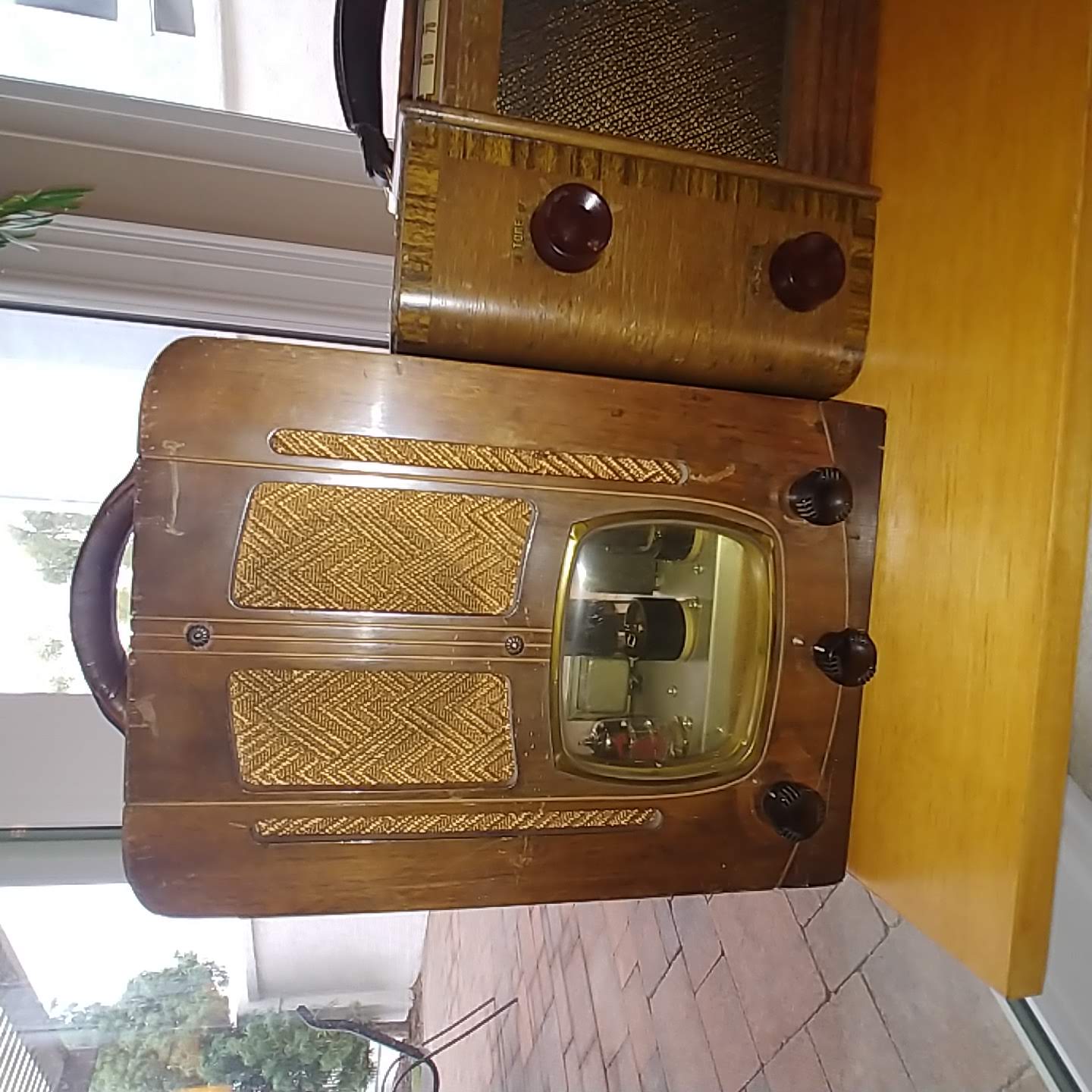
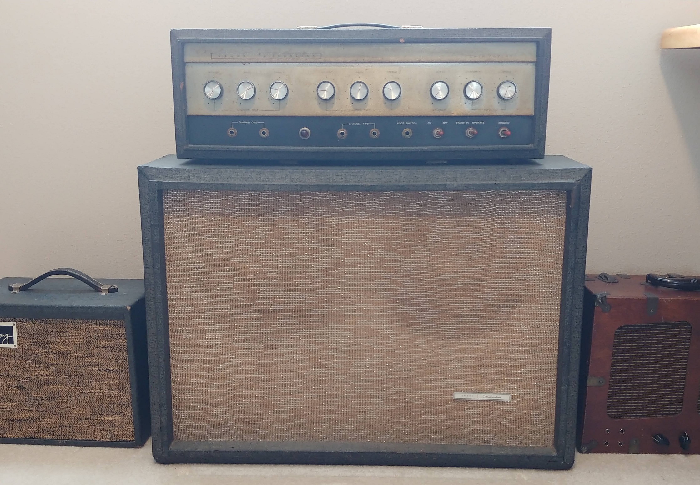
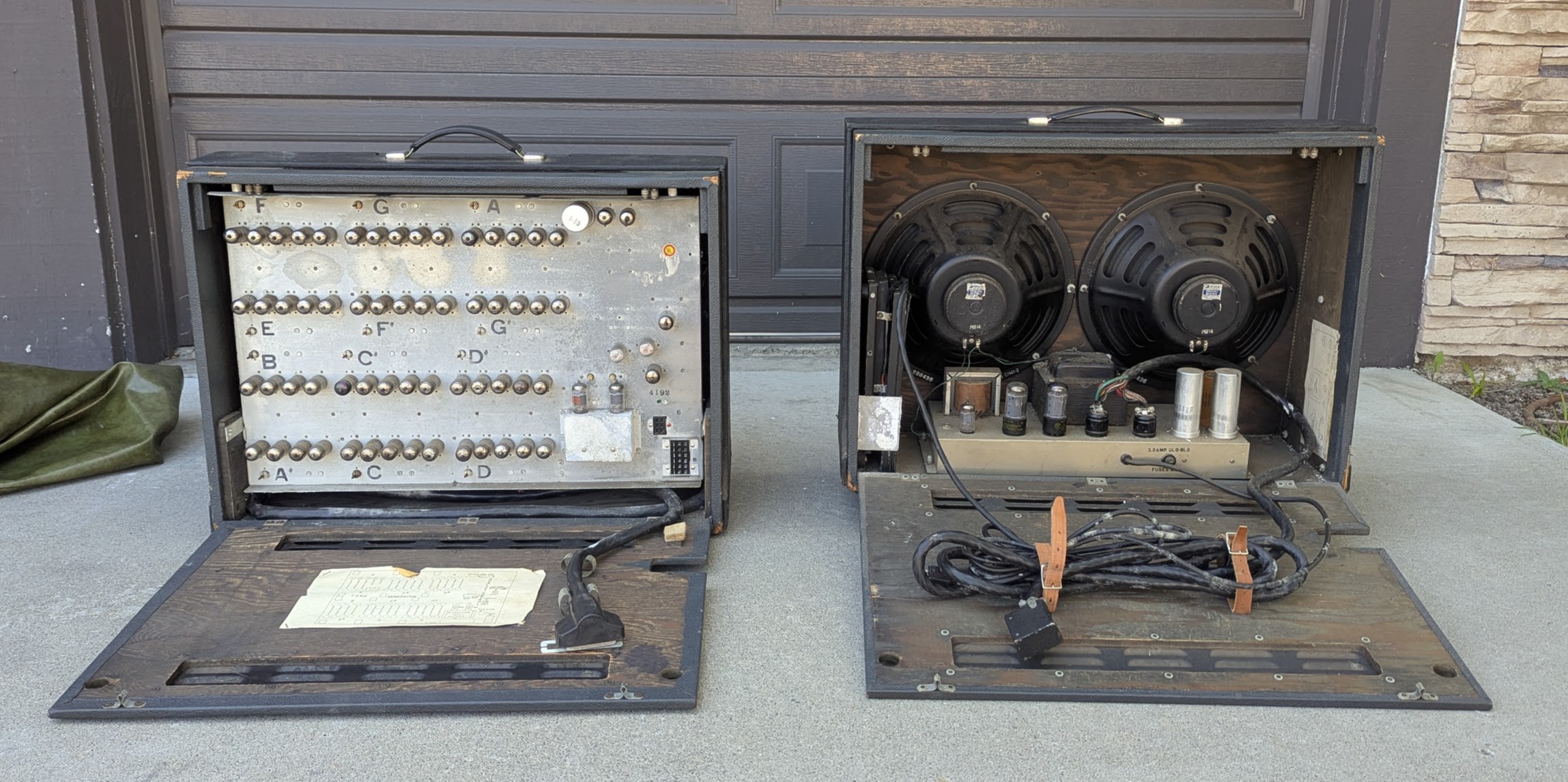
Electronic Accordion Project with just the two cabinet amp without the accordion, will be converted into a 212 amp with a 212 extension cabinet. The green cover is pretty time correct but only came with one. Its always difficult to destroy an original amp or radio in favor of a new design, but in this case there will be a significant future for the amp than if it was for accordion. When I was a young boy my parents had me taking accordion lessons and I eventually received a Cordovox. Just never really got into it as at that time it wasn’t cool to play accordion.

History
The Cordovox was an electronic accordion developed in the 1960s by the Chicago Musical Instrument Co. (CMI) and Farfisa, with some electronic designs licensed from Iorio Accordion Co. It combined the sounds of a traditional acoustic accordion with electronic organ tones and effects. The early models (CG-2/CG-3) were developed through collaboration between Farfisa and Lowrey Organ Co., with the organ section based on the Lowrey "Holiday Deluxe". Later models, like the CG-4 and CG-5, used solid-state electronics.
-
CMI, the parent company of Lowrey, partnered with Farfisa (Scandalli accordion section) to produce the Cordovox. The first three generations were a collaboration between Farfisa and Lowrey, with Lowrey providing the tone generator, amplifier, and other electronic components.
-
Cordovox was known for its ability to produce organ-like sounds, including tremolo and other effects, alongside the traditional accordion sound. Later models, like the CG-4 and CG-5, utilized solid-state electronics and were visually distinguishable by their bass button color schemes (black on white for CG-2/CG-4, and white on black for CG-3/CG-5). The Cordovox, while technologically advanced for its time, eventually became overshadowed by newer digital instruments, but it remains a significant example of early electronic accordion technology and a favorite among some musicians.
-
The Cordovox tone generator, particularly the earlier vacuum tube models, used rows of lamps (often neon lamps, as mentioned in one source) within the tone generation circuitry.
These lamps played a crucial role in creating the desired sound, specifically in producing sustain, according to Accordion Hub SA. Each voice tab or note would have a corresponding lamp, contributing to the overall tone and the way notes decayed over time.


The plan is to gut the tone generator cabinet and move the speakers and power amp from the speaker cab to the tone cab. This allows the use of the existing Cordovax control panel. The preamp from the tone Generator will be kept as well. The circuit design will be as original to the Cordovox as possible, changing the circuit only as needed to support guitar tone rather than accordion or mic.

Disassembly
The plan was to remove the tone generator/preamp/control panel from the Tone Generator cabinet and replace it with the 12” Jensen speakers and the power amp. The preamp from the control panel will be used.
The Tone Generator is out of the cabinet. It’s the epitome of point to point wiring, so complicated. There are 13 duplicate modules one for each scale note. Each of the modules includes five tube (2) 6X8 and (3) 6FH8
On the left side are the preamps for the Cordovox. I wish there was a published schematic, but alas no success.

Two of the 13 note modules. Five tubes on the top of the 3 line terminal strip and five tubes on the bottom.

Control Panel out and quite dirty


Tone Generator Cabinet cleaned and ready for new tenants. This baffle will be moved to the Extension cabinet, replaced by the 2x12 baffle and speakers from the Power Amp cabinet,

Power Amp/Speaker Cabinet is very dirty. Speakers, Baffle and Power amp will be removed.

Speakers are in great shape. Speaker code 220436 indicates Jensen (220) year 1964 (4) week 36 of manufacture.


Temporary Cordovox Repair Bench
This amp has so many large elements that a special bench was setup for repair. It was decided to draw a schematic as originally built. The design had many unusual quirks which might be a subject for a future article but for now the focus needs to be on creating the new guitar amp. First step is to modify the cabinets to accept speakers and the relocation of the power amp into the Tone Generator cabinet

Guitar 212 Amp Cabinet from the Tone Generator Cabinet
The Tone Generator will become home to the amplifier and the 2x12” speakers. This is because the TG cabinet already has the cutout for the control panel.. To accomplish this move, the baffle from the original Cordovox amp cabinet will be relocated in the TG cabinet and the TG baffle will be relocated to the Power Amp cabinet which will become the new extension cabinet. The TG baffle is removed and the grill cloth will be cleaned. This baffle is currently planned for the Extension cabinet. This Tone Generator baffle is ½” whereas the speak baffle is ¾”.

The original TG baffle had vertical slots cut into it. These were likely for cooling of the rows of neon light bulbs used to control tone and sustain.
Based on the available information, it's difficult to determine the exact reason for the two horizontal slots cut into the Cordovox tone generator baffle. However, some possibilities can be explored based on general acoustic principles and the characteristics of the Cordovox system:
-
Ventilation for tube-based tone generation: The early Cordovox tone generators were tube-based, meaning they produced a lot of heat. The slots could have served as vents to allow hot air to escape and prevent overheating of the delicate vacuum tubes, which were essential for generating the sounds.
-
Sound projection and diffusion: The slots might have been strategically placed to help project and diffuse the sound waves generated by the individual tone banks for each note/chord. This could potentially create a fuller and more even sound spread, especially considering the large number of tubes involved in producing the tones for each chord.
-
Unique acoustic character: The specific placement and design of the slots could have been an intentional part of the Cordovox's acoustic design to achieve a particular sonic character or to enhance certain frequencies.

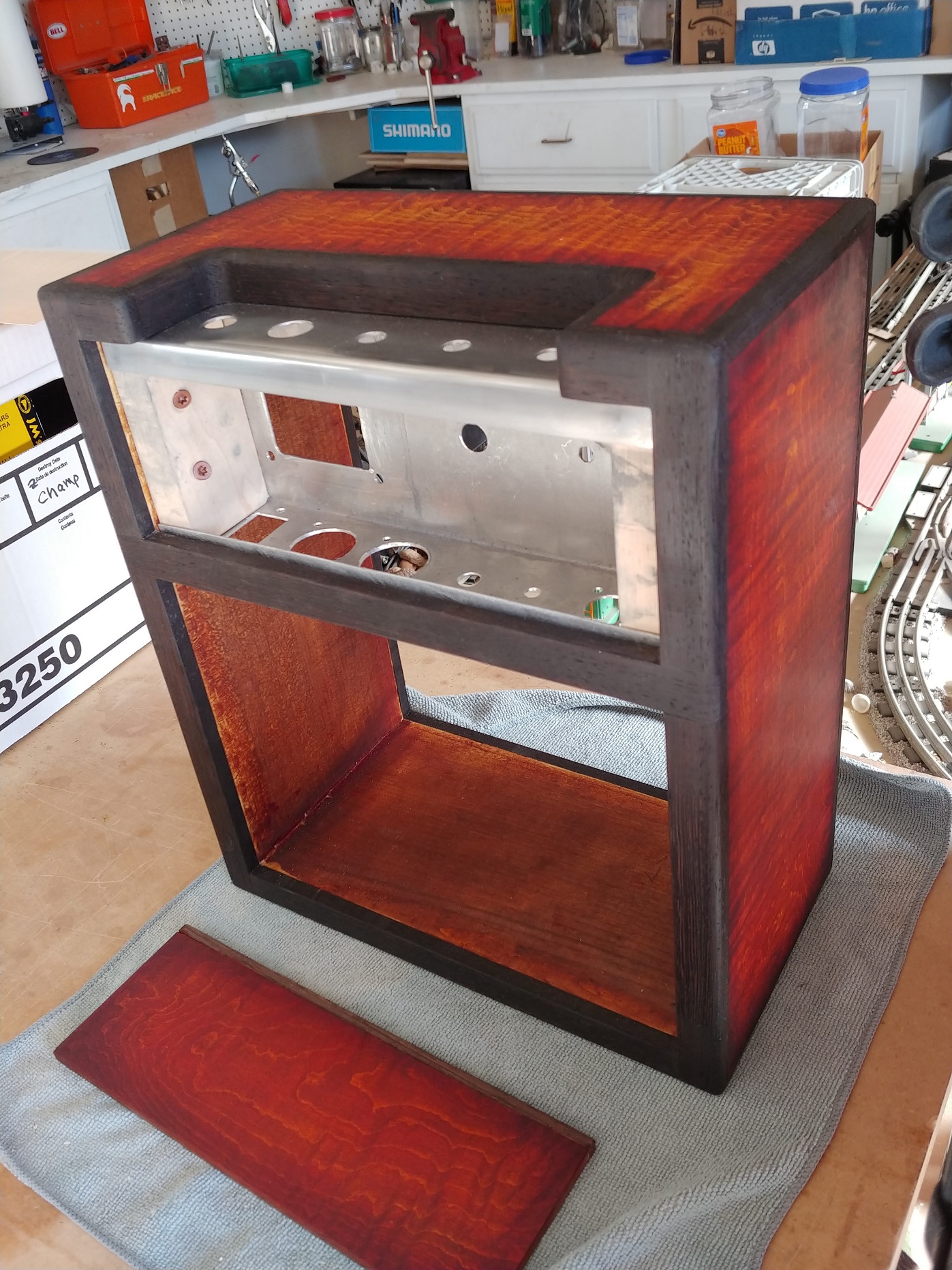
The original Cordovox 2x12 speaker baffle is used in the Guitar Amp cabinet along with the control panel, the two tube preamp chassis and on the bottom, the original Cordovox power amplifier.

The control panel is rotated from the Cordovox to expose the inside and for a better fit, the speaker baffle needed to be shaved at the top. The two tube preamp chassis (from the Tone Generator chassis) is mounted next to the control panel on the side of the input jacks.


Nice control panel fit, although reversed from the original Cordovox design.

Cordovox Speaker Design
Amplifier Cabinet to become the Extension Cabinet
Extension Cabinet New Speaker Baffle
The extension cabinet will receive two ceramic Jensens that match the original Cordovox speakers. In order to prepare the cabinet a new speaker baffle needed to be fabricated. IN order to stay true to the original Cordovox style and vibe, it was decided to modify the Tone Generator baffle to accept the new Jensens. Since the original baffle was thin at ⅜” and older plywood, I ½” baltic birch baffle was made and glued to the Tone Generator baffle.

Remove Rosette Screws
To remove the baffles, the rosette screws that hold the black tolex reinforcement cabinet trim need to be loosened and tapped flush with the inner surface, I did not need to remove them. Loosen and remove the rosette nut, If the rosette spins with the nut you will need to hold the rosette with a pliers. I was able to tap the screw with the nut creating a bit of space to grab the rosette. Careful not to scratch the rosette, but if you do a dab of black paint will help.
I also waxed all the screws and bolts to make them easier for next time.
Baltic Birch reinforcement baffle cut and ready for flat black

Original Baffle cutout to match the reinforcement baffle. Because of the original cutout it left a large gap between the speakers that needed to be filed. Cutouts from the original scrap were then glued in place. Then the two sections were glued to each other creating a very sturdy baffle for the new speakers


Vintage plywood on top and modern baltic birch below. Adding a modern speaker baffle with the looks and vibe of the original Cordovox

The new extension cab baffle fits nicely in the original Cordovox amp/speaker cabinet


Cleaning the Grill Cloth
The original grill cloth was filthy. It was removed and scrubbed with diluted simple green. Seemed like there were hundreds of stables that needed to be removed. Came out very good, showing the age related patina that is now a permanent part of its history.


Corner and Tolex Repair
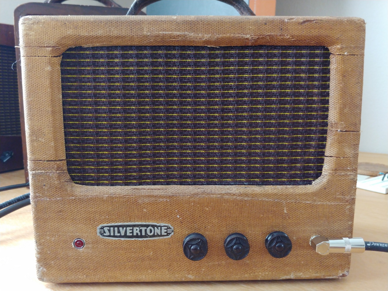
The approach to these damaged corners is to fill the missing material with plastic wood, sand smooth, reapply tolex recovered from inside the cabinet and then apply aging to match the rest of the cabinet. This was successfully accomplished on the Silvertone 1484 cabinet as well.


Power Amp
The power amp is shown below removed from the cabinet and located to a custom jig to hold it during circuit modification.


Grounding
Electrolytic Capacitors are all replaced and the grounding cleaned up. Cordovox had several ground points which could cause ground loops. This was cleaned up into three star grounds as indicated in the schematic. These are all labeled with purple tape in the figure.
G1 - the Power Supply and Power Amp
G2 - the Preamp, Preamp Power Supply and Control Panel
G3 - the Speaker and Output Transformer (only because it is at the other end of the Power Amp Chassis)
There are a couple of other grounding considerations:
-
Should the ground connection between the upper and lower chassis be kept, this is the bare wire connecting pin 8 and pin 3 on the 9pin connector to the left of the AC cable. It essentially connects G1 and G2 and might be a noise source.
-
Should having a separate ground star for speaker and OT G3 be connected into G1 for noise reduction

Output Transformer Secondary Snubber circuit
The resistor and capacitor connected across the secondary of a Cordovox output transformer likely serve as a Zobel network (also known as a snubber network or impedance equalization circuit).
Here's why it's included:
-
To stabilize the amplifier and prevent high-frequency oscillations: Output transformers, especially in tube amplifiers like the Cordovox, can exhibit stray inductance and capacitance. This can lead to ringing or parasitic oscillations at high frequencies, which can cause damage to components or introduce distortion into the audio signal. The Zobel network acts as a damping circuit to absorb or dissipate the energy that causes these oscillations.
-
To present a more consistent load to the transformer: Output transformers are designed to work optimally with a specific load impedance (typically 4, 8, or 16 ohms). However, the actual impedance of a speaker can vary depending on the frequency of the audio signal. The Zobel network, by smoothing out the impedance curve, helps the output transformer operate more consistently across the audible frequency range, leading to better sound quality.
-
To protect the amplifier's output stage: High voltage peaks can occur across the transformer windings, especially if the secondary is left open or experiences a mismatch with the load. The Zobel network, by providing a controlled path for these voltage spikes to dissipate, helps protect the output tubes and other components from damage.
In essence, the resistor and capacitor form a frequency-dependent load that helps to:
-
Dampen unwanted high-frequency resonances.
-
Improve the amplifier's stability.
-
Present a more consistent load to the output transformer, improving sound quality.
-
Protect the output tubes and associated components from damage due to high voltage spikes.
PreAmp and Control Panel
The preamp is housed in a small chassis from the Tone Generator that is relocated to the top of the Power Amp cabinet. It is connected to the control panel (also relocated to the Power Amp cabinet). The umbilical cable from the Power Amp to the Control panel made use of the original Cordovox cable which is sized to meet the dimension of the new layout. Additional signal cables connect the Volume Tone and Master Volume pots between the control Panel and the Preamp chassis.


The Extension Cable
Designed to match the original cabinet cover, the extension cabinet cable is 18g twisted pair in green with a straight and angled plug. Will add to the cool factor of this conversion. The amp will work with the extension cabinet plugged in as a 412 or without the extension cabinet as a 212.

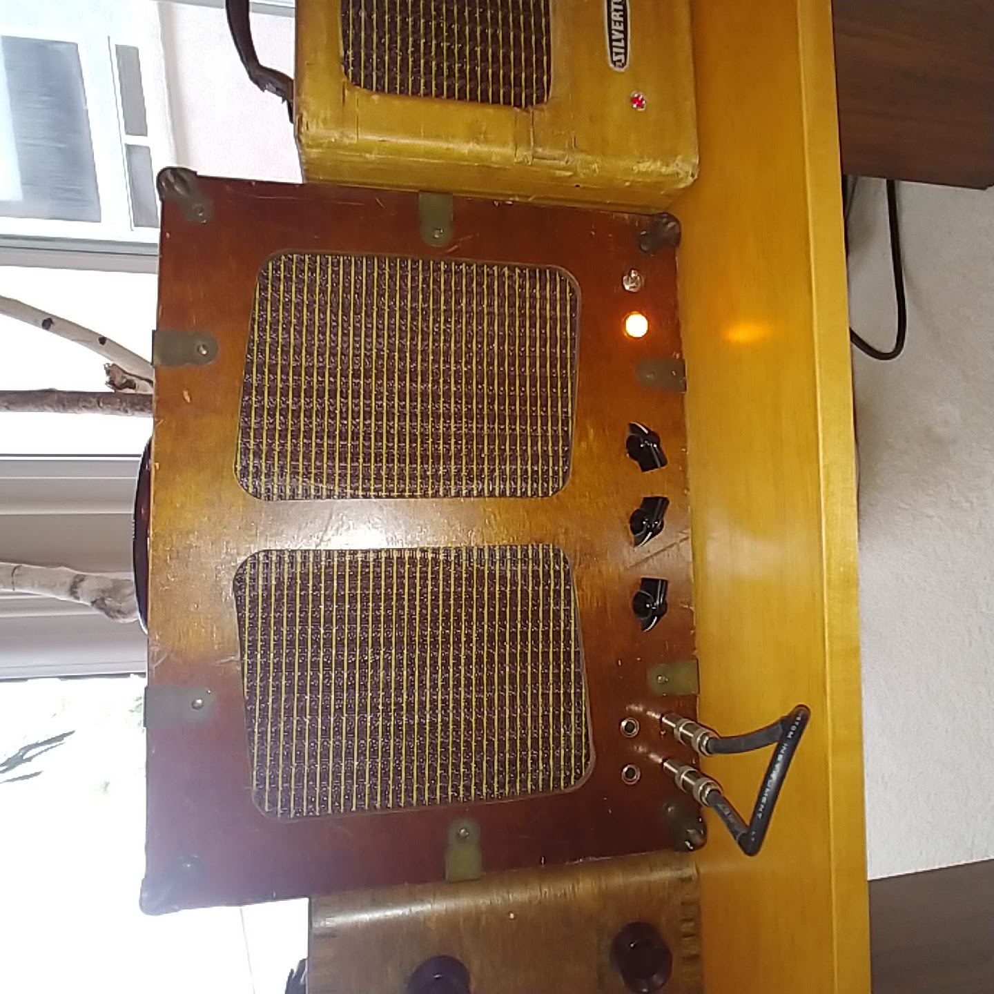
The Stack
In the picture, the Extension cabinet is on top because it is lighter. But then the control panel is not as accessible, So it will be reversed to allow the power amp Control panel to be on top.

Cordovox Conversion Schematic

Original Cordovox Redraw by scstill

Another suggested PreAmp for guitar amp
Why thermistors on Line?
Why switch on Neutral?
Why L2 on the 1st preamp stage grid?
Adding a parallel ext jack lowers impedance which is risky for the OT and Power tubes

Conversion References
https://noisemikers.com/cordovox-accordion-amp-conversion-with-schematics/
https://www.tdpri.com/threads/requesting-schematic-check.940338/
7591 Tube Datasheet https://frank.pocnet.net/sheets/168/7/7591.pdf
Full Wave Voltage Doubler https://www.electricalvolt.com/voltage-doubler/
Consideration for the Tone Generator Conversion
6X8 Tube Datasheet https://frank.pocnet.net/sheets/093/6/6X8.pdf
6FH8 Tube Datasheet https://frank.pocnet.net/sheets/127/6/6FH8.pdf
Use of 6X8 as Paraphase PI http://www.dogstar.dantimax.dk/tubestuf/paraph.htm
Cordovox History
https://accordionhubsa.co.za/cordovox-accordion-in-south-africa-and-history-of-instrument/